
Description
Hard-Numbers: Technical Specifications
- Analog Input Channels: 32 single-ended / 16 differential
- ADC Resolution: 16 bits (no missing codes guaranteed)
- Maximum Sample Rate: 500 kS/s (aggregate), 500 kS/s single channel
- Input Ranges: ±0.2 V, ±1 V, ±5 V, ±10 V
- Input Impedance: >10 GΩ (device on), 1,200 Ω (device off)
- CMRR: 100 dB (DC to 60 Hz)
- Absolute Accuracy: 2,190 μV warranted
- Analog Output Channels: 4
- Update Rate: 900 kS/s (1 channel), 840 kS/s (2 channels), 775 kS/s (3 channels), 719 kS/s (4 channels)
- AO Range: ±10 V
- AO Current Drive: ±5 mA
- Digital I/O: 48 bidirectional channels (32 hardware-timed Port 0, 16 PFI/Port 1/Port 2)
- Digital Max Clock Rate: 1 MHz (Port 0 only)
- Digital Output Current: 24 mA (P0), 16 mA (PFI/P1/P2)
- Counters/Timers: 4 × 32-bit
- Counter Max Frequency: 100 MHz source, 25 MHz external
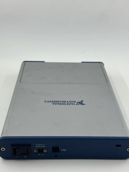
- Bus Interface: USB 2.0 Hi-Speed
- Timing Technology: NI-STC3 with independent analog/digital engines
- Input FIFO Size: 2,047 samples (AI), 8,191 samples (AO)
- Connectors: 128 screw terminals or 30 BNCs + 60 screw terminals
- Power Supply: 11-30 V DC external, 30 W max
- Power Consumption: Typically 12-18 W under load
- Warm-up Time: 15 minutes recommended
- Calibration Interval: 2 years
- Operating Temperature: 0°C to 50°C (32°F to 122°F)
- Dimensions: 26.4 × 17.3 × 3.6 cm (10.4 × 6.8 × 1.4 in.) screw terminal
- Weight: 1.445 kg (3 lb 3 oz) screw terminal, 1.803 kg (3 lb 15.6 oz) BNC

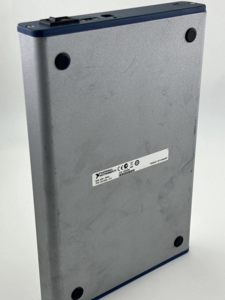
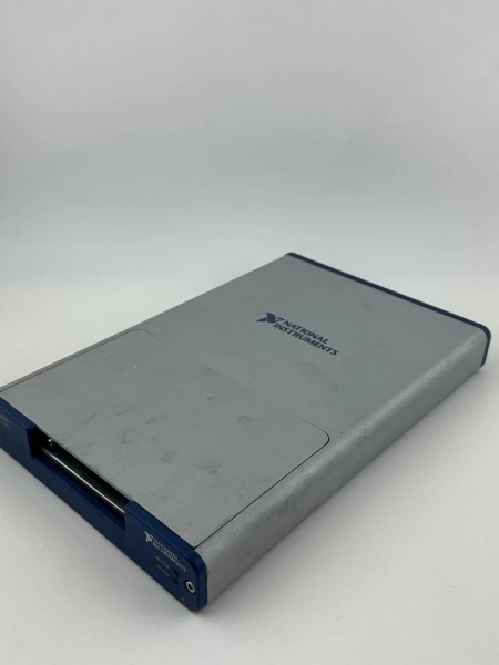
NI USB-6343
The Real-World Problem It Solves
When you need a portable data acquisition solution that combines high channel count, fast sampling, and flexible I/O without PCIe or PXI backplane constraints, this USB device provides benchtop performance in a field-deployable package. The NI-STC3 timing engine enables synchronized analog/digital/counter operations that would normally require chassis-based systems.
Where you’ll typically find it:
- Portable vibration and acoustic test rigs
- Laboratory data logging with mixed sensor types
- Automated test equipment for production lines
- University teaching labs and research projects
- Field service verification tools for industrial equipment
Bottom line: It delivers complete multifunction DAQ capabilities—32 AI, 4 AO, 48 DIO, 4 counters—in a USB-powered enclosure that survives laboratory environments and controlled field deployments.
Hardware Architecture & Under-the-Hood Logic
The USB-6343 uses the NI-STC3 ASIC for timing and synchronization, featuring independent analog and digital timing engines. A multiplexed ADC digitizes analog inputs while separate DACs drive analog outputs. Digital I/O lines route through programmable filters to the USB interface via the NI Signal Streaming architecture.
Signal flow and processing logic:
- Analog Input Stage: 32 channels route through input multiplexer to single 16-bit ADC with programmable gain.
- ADC Conversion: Multiplexed sampling at up to 500 kS/s aggregate, 2,047-sample FIFO buffers data.
- Analog Output Stage: 4 independent 16-bit DACs with 8,191-sample shared FIFO update at up to 900 kS/s.
- Digital I/O Engine: Port 0 (32 lines) supports hardware-timed waveform I/O up to 1 MHz; PFI/P1/P2 handle static or timing I/O.
- Counter/Timer Block: 4 × 32-bit counters with 127-sample FIFO for edge counting, PWM, encoder, frequency measurement.
- NI-STC3 ASIC: Manages independent analog and digital timing engines, retriggerable tasks, and signal routing.
- USB Interface: USB 2.0 Hi-Speed with NI Signal Streaming for concurrent bidirectional data transfer.
- Power Supply: External 11-30 V DC input regulated to internal rails; overvoltage protection on AI channels up to ±25 V.
- Trigger Routing: PFI terminals accept external triggers or route internal timing signals between subsystems.
NI USB-6343
Field Service Pitfalls: What Rookies Get Wrong
Insufficient Warm-up Before Precision Measurements
The device requires 15 minutes of warm-up to achieve specified accuracy. New technicians often start critical measurements immediately after power-up, resulting in drift and offset errors.
- Field Rule: Power up the device at least 15 minutes before precision measurements. If ambient temperature changes significantly during the day, allow additional warm-up time after thermal stabilization.
Exceeding Analog Input Voltage Limits
Maximum working voltage is ±11 V (signal + common mode). Overvoltage protection handles ±25 V on up to two pins temporarily, but sustained overvoltage damages protection diodes.
- Quick Fix: Verify sensor output ranges with a multimeter before connecting. Use external voltage dividers or attenuators for signals exceeding ±11 V. If you suspect overvoltage occurred, check the device with known good voltages before returning to service.
Overloading Analog Outputs
The ±5 mA current drive limit is often ignored when driving low-impedance loads. Exceeding this causes output voltage sag or damage.
- Field Rule: Calculate load impedance before connecting AO channels. Minimum load impedance is 2 kΩ for full ±10 V swing. For lower impedance loads, use external op-amp buffers. Never connect AO directly to speakers or motors.
USB Bandwidth Saturation
Streaming all channels at maximum rates saturates USB 2.0 bandwidth, causing USB errors or data loss. The device supports 500 kS/s aggregate AI and 900 kS/s aggregate AO, but not simultaneously at maximum rates.
- Field Rule: Calculate total bandwidth before deployment. USB 2.0 Hi-Speed handles approximately 35-40 MB/s sustained. Reduce sample rates or disable unused channels if experiencing USB transfer errors. Use shielded USB cables under 3 meters for reliable operation.
Incorrect Grounding in Differential Mode
Connecting floating signal sources without proper grounding creates ground loops and CMRR degradation. The 100 dB CMRR assumes proper differential connection.
- Field Rule: For floating sources, connect the negative terminal to AI GND at a single point. Use twisted-pair shielded cables with the shield grounded at the DAQ end only. Avoid creating multiple ground paths between the device under test and the USB-6343.
Ignoring Digital Input Filter Settings
Hardware-timed digital I/O requires proper debounce filtering. Default filters (160 ns, 10.24 μs, 5.12 ms) must match signal characteristics or you’ll miss edges or catch bounce.
- Field Rule: Select appropriate debounce filter in NI-DAQmx configuration. For mechanical switches, use 5.12 ms or custom debounce. For clean TTL signals, disable filters or use 160 ns. Verify signal integrity with an oscilloscope before running critical digital measurements.
Power Supply Voltage Drop Under Load
Long power cables or undersized supplies cause voltage drop below 11 V minimum, resulting in unpredictable behavior or shutdowns. The device requires 30 W at full load.
- Field Rule: Use 18 AWG or larger wire for power cables longer than 2 meters. Measure voltage at the device power terminals under full load—if below 11 V, reduce cable length or gauge. Use the specified Phoenix Contact MC 1,5/2-GF-3,5 BK connector or equivalent.


