
Description
Hard-Numbers: Technical Specifications
- Matrix Configuration: 8 × 16 (2-wire)
- Compatible Module: NI PXI-2529, NI PXIe-2529 High-Density Matrix Switch
- Connection Type: Screw terminals
- Maximum Signal Voltage: 150 V (CAT I)
- Maximum Switching Current: 1 A per channel (via PXI-2529)
- Maximum Carry Current: 2 A per channel (via PXI-2529)
- Impulse Voltage Rating: 800 V (tested surge withstand)
- Measurement Category: CAT I
- Relay Type: Electromechanical, latching (silver/gold contacts – via PXI-2529)
- Relay Operate Time: 1 ms typical, 3.4 ms maximum (via PXI-2529)
- Thermal EMF: < 9 μV (via PXI-2529)
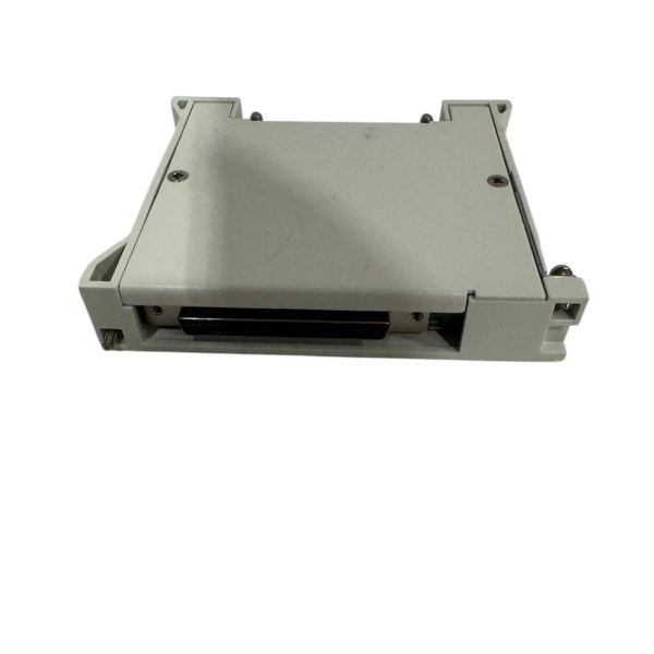
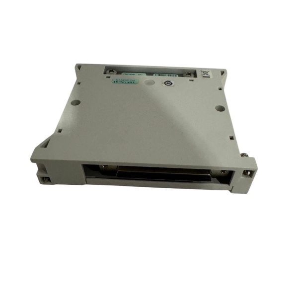
- Connector Mounting: 200-pin LFH Matrix 50 receptacle (mating to PXI-2529)
- Dimensions: Approximately 0.77 in × 3.3 in × 4.1 in (19.5 mm × 83.8 mm × 104.1 mm)
- Weight: 0.46 kg (1.01 lb)
- Strain Relief: Integrated strain-relief bar
- Ground Terminal: Safety ground lug
- Mounting Hardware: Two jackscrews for firm connection to switch module
- Pollution Degree: 2
- Operating Temperature: 0°C to 50°C (typical, verify with PXI-2529 specs)
- Relative Humidity: 5% to 85% noncondensing
- Maximum Altitude: 2,000 m (operating)
- Shock and Vibration: Rated to MIL-PRF-28800F Class 3 (via PXI-2529)
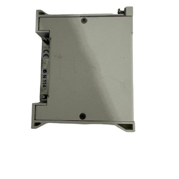
- Compliance: IEC 61010-1, EN 61010-1, UL 61010-1, CSA 61010-1, RoHS compliant
The Real-World Problem It Solves
High-density matrix switching systems with ribbon cable headers and flying leads create nightmare maintenance scenarios on the factory floor. Techs spend hours tracing individual wires, dealing with loose connections, and fighting cable strain every time a DUT swap happens. The TB-2635 eliminates the ribbon cable mess by providing direct screw terminal access to your 8×16 matrix—wires terminate once, stay put, and you’re swapping DUTs in minutes instead of hours.
Where you’ll typically find it:
- Automotive ECU test stations where 8 devices under test need simultaneous 2-wire signal routing from a single PXI-2529 matrix
- Semiconductor wafer probe systems requiring reliable 2-wire connections to 16 test sites with 8 row configurations
- Cable harness test racks where operators need quick-disconnect screw terminals for frequent DUT changes without re-terminating ribbon cables
Bottom line: This terminal block turns your PXI-2529 matrix into a field-serviceable switching panel—no more ribbon cable frustration, just screw terminals that stay connected through temperature cycles and vibration.
Hardware Architecture & Under-the-Hood Logic
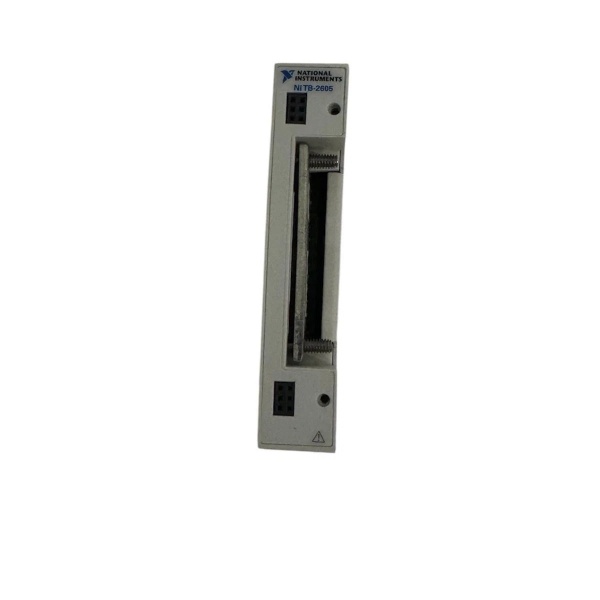
The TB-2635 is a passive front-mount terminal block with no active electronics. It provides mechanical and electrical translation between the PXI-2529’s 200-pin high-density front-panel connector and individual screw terminals for 2-wire signal access. The terminal block houses the internal PCB routing that configures the PXI-2529 as an 8×16 (2-wire) matrix topology. Signal paths flow from external devices through screw terminals, across the internal PCB traces to the mating 200-pin connector, and into the PXI-2529’s relays. The strain-relief bar and safety ground lug provide mechanical stability and ESD/grounding protection.
- External signal input: External devices connect to screw terminals on the TB-2635 front panel (rows R0-R7, columns C0-C15)
- PCB routing: Internal PCB traces route screw terminal connections to the appropriate pins on the 200-pin LFH Matrix 50 receptacle
- Matrix configuration: PCB layout configures PXI-2529 as 8×16 (2-wire) matrix, mapping 8 rows and 16 columns across the terminal block
- Jackscrew mounting: Two jackscrews secure the terminal block to the PXI-2529 front-panel connector, ensuring reliable electrical contact
- Strain relief: Integrated strain-relief bar clamps external wires, preventing mechanical stress on screw terminals and PCB connections
- Ground connection: Safety ground lug provides chassis ground connection for ESD protection and noise reduction
- Signal transmission: 2-wire signals flow through the terminal block to PXI-2529 relays, which switch connections per matrix topology
- Trigger connections: Trigger screw terminals (if present) route PXI trigger lines (0-7) for synchronized switching operations
- Relay control: PXI-2529 firmware/hardware controls internal electromechanical latching relays based on matrix configuration from TB-2635 routing
- Signal output: Switched signals return through TB-2529 internal routing to PXI-2529 backplane or front-panel trigger outputs as configured by test application
NI TB-2635 778839-01
Field Service Pitfalls: What Rookies Get Wrong
Over Tightening Screw Terminals and Stripping the Threads
Techs treat TB-2635 screw terminals like they’re tightening lugs on a 500 MVA transformer, cranking down until the torque wrench screams. These are small signal terminals—over-tightening strips the threads, cracks the terminal housing, and creates intermittent connections that fail under vibration. You’ll spend hours debugging “random” matrix switching faults caused by stripped terminals.
- Field Rule: Use a properly calibrated torque screwdriver. NI specifies 0.4 N·m to 0.6 N·m for terminal block screw terminals (3.5 to 5.3 in·lb). If you don’t have a torque screwdriver, “finger tight plus 1/8 turn” gets you close—no breaker bars. Stripped threads mean replacing the entire terminal block, not just the screw.
Neglecting Strain Relief and Letting Vibration Kill Connections
Engineers terminate wires to screw terminals but ignore the integrated strain-relief bar. In vibration-heavy environments (test racks near hydraulic pumps, stamping presses), wire vibration works terminal screws loose. After a week of operation, you’re chasing intermittent connections and blaming the PXI-2529 relays when the culprit is mechanical strain on unsheathed wires.
- Field Rule: Clamp every wire in the strain-relief bar before tightening terminal screws. Leave 1-2 inches of slack between the bar and terminals—no taut wires. The strain-relief bar isn’t optional; it’s mandatory for vibration environments. If your terminal block doesn’t have a bar, use cable ties to bundle wires and secure them to the chassis near the block.
Mixing High and Low Voltage on Adjacent Terminals
Technicians wire CAT I signals (≤150 V) next to CAT II/III signals (>150 V) on adjacent screw terminals, thinking “it’s all low voltage.” IEC 61010-1 prohibits mixing measurement categories on the same terminal block without isolation barriers. If you’re switching 120 V AC mains next to 5 V sensor signals and a fault occurs, the 5 V circuit sees 120 V—fried DUT, damaged PXI-2529, safety hazard.
- Quick Fix: Segregate voltages by measurement category. Keep CAT I signals (≤150 V) on one bank of terminals and higher voltages on separate isolated terminal blocks. If you must mix voltages, ensure you understand creepage and clearance distances—or better yet, use separate switching modules for different voltage levels. One fault shouldn’t cascade through your entire test system.
Jack Screw Mounting Without Verifying Connector Alignment
Mechanics force the TB-2635 onto the PXI-2529 front-panel connector by tightening only one jackscrew, hoping the second will “pull it into alignment.” Misalignment bends connector pins, creates poor contact, and eventually damages the 200-pin LFH Matrix 50 receptacle. You’ll see random switching failures, high contact resistance, and eventually a dead PXI-2529 front panel.
- Field Rule: Hand-tighten both jackscrews equally—2-3 turns on the left, 2-3 on the right, repeat until snug. No force. If the block doesn’t seat flush, 终止 and realign. Visual inspection: ensure no gaps between block face and PXI-2529 front panel. Bent pins mean expensive repairs—take 30 seconds to align correctly instead of 3 weeks waiting for RMA.
Connecting Beyond CAT I Rating Without Isolation
Techs connect 230 V AC mains to TB-2635 terminals, assuming “150 V rating is just a guideline.” This terminal block is rated CAT I (≤150 V) per IEC 61010-1. Applying CAT II/III mains voltages exceeds insulation, creepage, and clearance ratings. Arc flash risks, fire hazards, and catastrophic failure when voltage spikes occur. Safety interlocks won’t save you—you’re violating product specs.
- Field Rule: Never exceed 150 V on TB-2635 terminals. For higher voltages, use isolated switching modules designed for CAT II/III (NI PXIe-2503, PXIe-2508). The 800 V impulse rating is for surge withstand, not continuous operation. If your test requires 230 V switching, use the right hardware—this block isn’t built for it. Period.
Forgetting Ground Lug Connection in Noisy Environments
Installers leave the safety ground lug floating in high-EMI environments (motor drives, RF transmitters, welding equipment). Without chassis ground, the terminal block acts as an antenna, picking up noise that couples into your matrix switching. You’ll see 50/60 Hz hum, signal spikes, and measurement jitter that disappears when you touch the block with your hand—classic ground loop symptom.
- Quick Fix: Connect the safety ground lug to chassis ground using a heavy-gauge wire (minimum 18 AWG, prefer 14 AWG). Use star washers to bite through paint for solid metal contact. Grounding isn’t optional in noisy environments—it’s mandatory for signal integrity. If noise persists, add ferrite beads on signal wires near the terminals.
Commercial Availability & Pricing Note
Please note: The listed price is for reference only and is not binding. Final pricing and terms are subject to negotiation based on current market conditions and availability.


