
Description
Hard-Numbers: Technical Specifications
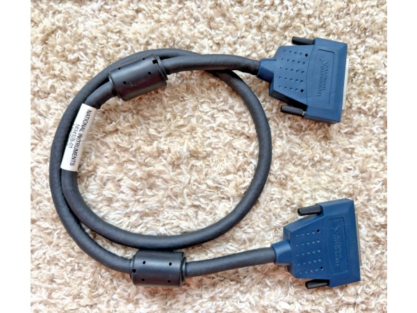
- Connector Type: 68-Pin D-SUB Female (both ends)
- Cable Length: 1 m (183432-01); available in 0.4 m, 2 m, 5 m, 10 m variants
- Cable Type: Shielded digital cable with twisted pair wiring
- Shielding: Multi-layer foil and braid shielding for EMI/RFI protection
- Wire Configuration: Twisted pair construction for crosstalk reduction
- Compatible Modules: NI 6533, NI 6534 (digital I/O); NI 660x, NI 661x (counter/timer)
- Compatible Accessories: 68-pin accessories including SCB-68, TBX-68, BNC-2090, SCC-68, CB-68LPR
- Weight: 0.34 kg (183432-01, 1 m variant)
- Country of Origin: China
- Tariff Classification: 85444290
- US ECCN: EAR99
- EU ECCN: NLR
- RoHS Compliant: Yes (6 substances)
- RoHS Phthalates Compliant: Yes
- SVHC Status: No SVHC (as of July 8, 2021)
- Operating Temperature: 0°C to 50°C (typical for NI cables; verify with module specifications)
- Connector Material: Metal shell with gold-plated contacts (typical for NI D-SUB connectors)
- Current Rating: Up to 2 A per pin (via connected module; verify with module specifications)
- Voltage Rating: Up to 30 V (signal level; verify with module specifications)
- Compliance: IEC 61010-1, EN 61010-1, UL 61010-1, CSA 61010-1 (via connected accessories)
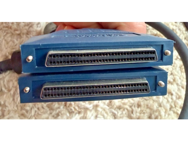
SH68F-68F 183432-01
The Real-World Problem It Solves
High-speed digital I/O and counter/timer applications in industrial environments suffer from EMI-induced data corruption, false triggers, and timing errors when using unshielded or poorly shielded cables. Techs spend hours debugging ghost signals, bit errors, and missed pulses caused by noise coupling from adjacent motor drives, VFDs, and RF transmitters. The SH68F-68F eliminates these issues with multi-layer shielding and twisted-pair construction—your digital signals stay clean, timing stays accurate, and debug sessions shrink from days to minutes.
Where you’ll typically find it:
- Automated test stations running NI 6533/4 digital I/O modules for high-speed pattern generation and acquisition in automotive ECU testing
- Production line test systems using NI 660x/661x counter/timer modules for frequency measurement, encoder reading, and pulse counting near heavy machinery
- Research labs and calibration facilities connecting DAQ devices to 68-pin terminal blocks (SCB-68) in environments with significant electrical noise
Bottom line: This cable is your noise insurance for high-speed digital signals—multi-layer shielding and twisted pairs protect your data integrity where unshielded cables fail, preventing EMI-induced test failures and saving hours of troubleshooting time.
Hardware Architecture & Under-the-Hood Logic
The SH68F-68F is a passive cable assembly with no active electronics. It consists of individual wire pairs twisted together and bundled within a multi-layer shield enclosure—foil shield for high-frequency noise rejection and braid shield for low-frequency EMI protection. The 68 wires connect pin-to-pin between two 68-pin female D-SUB connectors, maintaining signal integrity through controlled impedance and minimal crosstalk. Twisted-pair configuration reduces differential noise pickup between adjacent signal pairs, while the overall shield provides common-mode noise rejection. The cable jacket offers mechanical protection and chemical resistance for industrial environments.
- Signal input from module: Digital signals exit NI 6533/4 or NI 660x/661x module through 68-pin male connector
- First connector contact: 68-pin female D-SUB connector mates with module’s male connector, establishing electrical contact
- Twisted-pair routing: Individual wire pairs (typically adjacent digital I/O lines) are twisted together throughout cable length
- Foil shielding application: Aluminum foil wrap encloses twisted pairs, providing high-frequency EMI/RFI attenuation
- Braid shielding application: Braided copper shield over foil, offering low-frequency noise protection and mechanical durability
- Drain wire connection: Shield drain wire connects to connector shells, providing ground reference for shield effectiveness
- Cable routing: Shielded wire bundle travels through cable jacket, protected from abrasion and environmental contaminants
- Second connector contact: Signal wires and shield drain wire terminate at destination 68-pin female D-SUB connector
- Signal output to accessory: Digital signals pass through connector to 68-pin accessory (SCB-68, TBX-68, BNC-2090)
- Shield termination: Connector shells ground to chassis via accessory ground, completing shield return path for EMI currents
SH68F-68F 183432-01
Field Service Pitfalls: What Rookies Get Wrong
Exceeding Cable Length and Timing Signal Degradation
Engineers run 5-meter cables for high-speed digital I/O applications designed for 1-meter runs, assuming “digital is digital, length doesn’t matter.” Transmission line effects, signal reflections, and propagation delays accumulate over distance—setup/hold times fail, clock edges smear, and data corruption occurs. You’ll see intermittent bit errors at 10 MHz that disappear when you swap in a 1-meter cable.
- Field Rule: Follow NI cable length recommendations for your data rate. For NI 6533/4 high-speed digital I/O (up to 20 MHz), stick to 1-2 meter maximum. Use 5-meter cables only for low-speed applications (<1 MHz) or verify timing margins with oscilloscope. If you need long runs at high speed, consider repeaters or signal conditioning. Cable length matters—don’t discover timing violations during production testing.
Poor Shield Grounding and Creating Ground Loops
Technicians connect the cable shield drain wire to both the module and accessory chassis grounds, creating multiple ground paths. In systems with potential differences between grounds, ground loops flow current through the shield, inducing noise into signal wires. You’ll measure 50/60 Hz hum on digital lines, false triggers on counter inputs, and mysterious bit errors that correlate with equipment startup.
- Quick Fix: Ground the shield at one end only—typically at the DAQ module or source end. Leave the accessory end floating or connected through a capacitor for high-frequency grounding. Use isolated terminal blocks if ground potential differences exist. One shield ground point eliminates ground loops while maintaining EMI protection. Multiple grounds create noise pathways, not cleaner signals.
Mixing Shielded and Unshielded Cables in Same System
Techs replace a single failed cable with an unshielded ribbon cable (R68-68) because “it’s cheaper and fits.” In systems designed for shielded operation, mixing cable types creates impedance mismatches and differential noise susceptibility. The unshielded cable becomes an antenna, picking up EMI that couples back into shielded portions through shared connectors. Your test passes with shielded cables, fails intermittently with one unshielded link.
- Field Rule: Maintain cable consistency throughout the signal path. If your system uses SH68F-68F shielded cables, replace failures with shielded equivalents. Mixing shielded and unshielded cables violates system design assumptions about noise immunity. Cost savings on one cable disappear when debug time exceeds cable price difference. Use the right cable—system-wide shielding is designed as an integrated solution.
Straining Connector Shells with Cable Tension
Installers route cables with sharp bends or pull them tight between rack-mounted equipment, placing mechanical stress on D-SUB connector shells. Over time, shell deformation causes intermittent pin contact, cracked solder joints, or complete connector failure. You’ll wiggle the connector and see connections come and go—classic symptom of mechanical strain on solder joints.
- Field Rule: Maintain minimum bend radius (typically 10× cable diameter, ~10 mm for SH68F-68F). Leave service loops at connectors for strain relief. Use cable ties to support cable runs—don’t rely on connectors to bear tension. If you need to pull cables tight, you’re routing wrong. Connector shells aren’t strain relief—they’re electrical contacts. Mechanical stress means premature failure.
Ignoring Twisted-Pair Pairing and Swapping Wires
Techs create custom breakout cables or repair damaged SH68F-68F cables by untwisting pairs and swapping wires to match pinouts. Twisted-pair design assumes specific pairings for differential signaling and crosstalk reduction—mixing wires between pairs destroys noise immunity. Your cable tests good on ohmmeter (pins connect), but fails under EMI stress or high-speed data rates due to loss of differential rejection.
- Field Rule: Preserve twisted-pair groupings when modifying or repairing cables. Document which pins belong to which twisted pair—NI provides pinout diagrams showing pair assignments. If you must swap wires, swap entire pairs, not individual wires within pairs. Differential noise immunity depends on balanced pair geometry. Random wire reassignments turn a shielded cable into an unshielded one electrically.
Connector Shell Corrosion in Humid Environments
Facilities in coastal or high-humidity areas install cables without protecting D-SUB connector shells from moisture and salt spray. Shell corrosion increases contact resistance, creates noisy connections, and eventually causes open circuits. You’ll measure intermittent connections that correlate with humidity levels or salt air exposure—cleaning contacts temporarily fixes the problem until corrosion returns.
- Quick Fix: Apply dielectric grease to connector shells before mating in humid or corrosive environments. Use sealed connector boots or wrap connections with self-amalgamating tape for outdoor installations. Schedule periodic connector cleaning and inspection for marine environments. Corrosion kills connections faster than EMI—prevent it upfront. If you see green deposits on shells, the cable’s already compromised.
Commercial Availability & Pricing Note
Please note: The listed price is for reference only and is not binding. Final pricing and terms are subject to negotiation based on current market conditions and availability.


