
Description
Hard-Numbers: Technical Specifications
-
Topology: 16×1 multiplexer (one COM, 16 CH inputs, all 50 Ω)
-
Bandwidth (-3 dB): 2.5 GHz (typical, 50 Ω system)
-
Impedance: 50 Ω ±2 Ω (characteristic, all ports)
-
VSWR: <1.3:1 (DC to 1 GHz), <1.6:1 (1-2 GHz), <2.0:1 (2-2.5 GHz)
-
Insertion Loss: <0.5 dB (DC to 500 MHz), <1.5 dB (2.5 GHz)
-
Crosstalk: <-70 dB (DC to 100 MHz), <-40 dB (1 GHz), channel-to-channel
-
Switching Time: <1 ms (relay operate/release, typical)
-
Switch Type: Latching coaxial relays (failsafe to open on power loss)
-
Max Input Power: 30 W (DC to 100 MHz), derates to 10 W at 2 GHz
-
Max Input Voltage: 42 Vrms (DC to 60 Hz), 30 Vrms (RF)
-
Switch Life: 10 million mechanical cycles, 100,000 cycles at full RF power
-
Connectors: SMB female (COM, CH 0-15), 50 Ω terminated when open
-
Operating Temperature: 0°C to +50°C (calibrated), -20°C to +70°C storage
-
Power Draw: 3.5W typical (relay coil drive), 12W max (all relays energized)

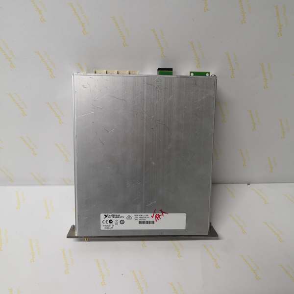
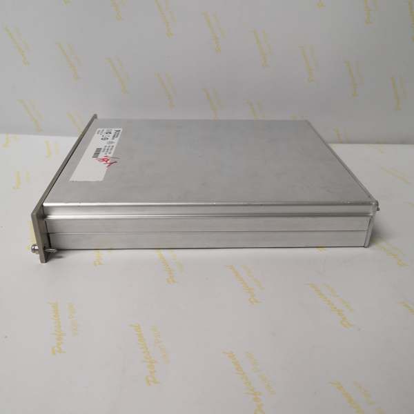
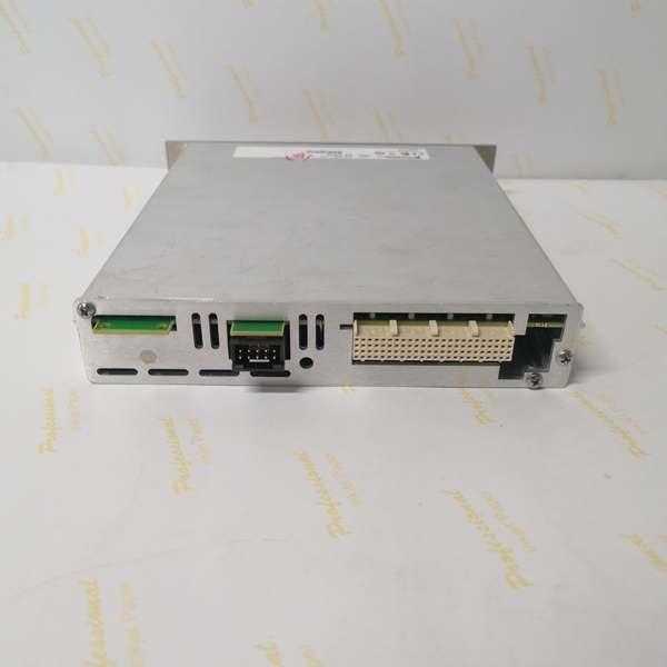
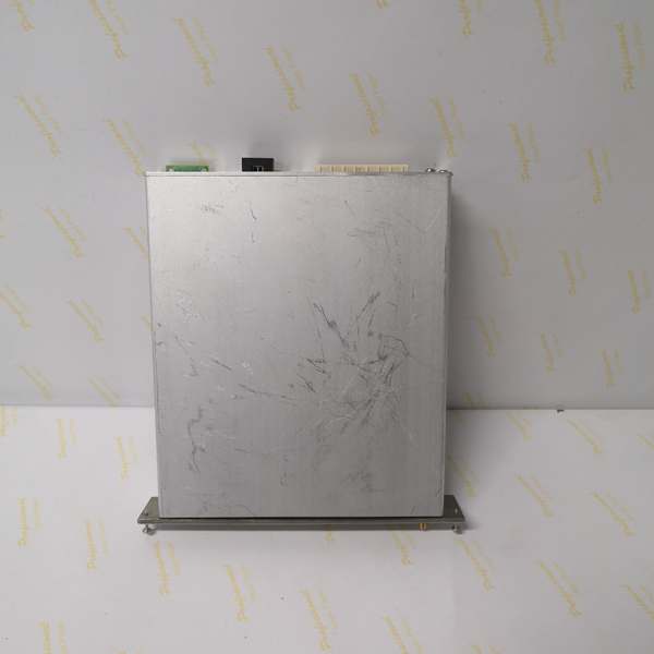
NI SCXI-1193
The Real-World Problem It Solves
General-purpose relay modules have 100 MHz bandwidth if you’re lucky. Their contact impedance bounces around, and they don’t terminate when open—signal reflections turn your clean 1 GHz clock into a ringing mess. The SCXI-1193 is built like RF test gear: 50 Ω coaxial construction, proper termination, and crosstalk specs that let you switch 16 RF sources into one spectrum analyzer without the “which channel is leaking?” guessing game.
Where you’ll typically find it:
-
RF production test: Switching 16 antenna ports into one vector network analyzer for S-parameter testing; VSWR <1.3 keeps cal valid.
-
High-speed digital validation: Routing PCIe or SATA test points to a scope; 2.5 GHz bandwidth handles 3rd harmonic of 5 Gbps signals.
-
Radar/EW system test: Distributing LO or IF signals in phased array calibration setups; latching relays hold state during power glitches.
Bottom line: It’s a programmable RF patch panel that lives in your SCXI chassis, not a rat’s nest of SMA cables.
Hardware Architecture & Under-the-Hood Logic
This module is essentially a programmable 16-throw coaxial switch. Each channel is a latching coaxial relay with 50 Ω center conductor and shielding throughout. The COM port is always terminated in 50 Ω—when you switch from CH 3 to CH 7, CH 3 sees 50 Ω (not open circuit), preventing reflections that would bounce back and corrupt the signal you just left.
-
Signal path: CH n input → coaxial relay contact → COM output. All paths 50 Ω ±2 Ω, PTFE dielectric, silver-plated contacts.
-
Relay control: Latching coils (set/reset) driven by SCXI backplane digital lines; no holding power required once switched. Default state: all relays open (COM terminated, all CH inputs see 50 Ω load).
-
Termination: COM port always 50 Ω to backplane; unused CH inputs see 50 Ω termination resistors when their relay is open—no stubs, no reflections.
-
Shielding: Individual coax shields isolated from module ground until CH selected; minimizes crosstalk in high-density RF environments.
-
SCXI integration: Module resides in SCXI-1000/1001 chassis; controlled via SCXI bus from DAQ device or PXI/PCI SCXI controller. No direct PXIe/PXI interface—must use SCXI controller.
NI SCXI-1193
Field Service Pitfalls: What Rookies Get Wrong
Hot-Switching RF Power
These are coaxial relays, not solid-state switches. Hot-switching 10W at 1 GHz welds contacts in 1000 cycles instead of 10 million. The arc pits the silver plating, VSWR degrades, and suddenly your “50 Ω” path looks like 75 Ω with a series inductance.
-
Field Rule: Always remove RF power before switching. Use external sequencing: disable PA → wait 10 ms → switch SCXI-1193 → wait 10 ms → re-enable PA. If you must hot-switch, keep power under 100 mW and accept reduced relay life. Monitor VSWR monthly in production; >1.5:1 at 500 MHz means contact degradation—replace the relay block or entire module.
Ignoring the SCXI Controller Requirement
This is an SCXI module, not PXI. It plugs into an SCXI-1000 chassis and talks via the SCXI parallel bus to a DAQ card (PCI/PXI) or SCXI-1600 USB controller. Rookies try to slot it into a PXIe chassis and wonder why it doesn’t show up in MAX.
-
Quick Fix: Verify your architecture: SCXI-1193 → SCXI-1000 chassis → SCXI cable → DAQ device (PCI/PXI) or SCXI-1600. The module has no direct PXIe interface. If you need PXIe control, use the SCXI-1600 USB controller and USB-to-PXIe bridge, or migrate to the PXI-2548/2549 RF multiplexers. Check SCXI cable seating—the 68-pin D-sub is prone to bent pins in industrial environments.
Mismatched Impedance in the System
The module is 50 Ω. Your source is 50 Ω. Your analyzer is 50 Ω. But that 3-foot BNC cable you grabbed from the parts bin is 75 Ω CATV coax. Now you’ve got a mismatch that causes 4% reflection at each junction—enough to ghost your measurements.
-
Field Rule: Use only 50 Ω coax (RG-58, RG-174, or better, LMR-240 for low loss). Verify cable impedance with a TDR if unsure. Terminate unused CH inputs in 50 Ω (the module does this internally when relay is open—don’t add external tees). For 75 Ω systems (video, CATV), use a minimum-loss pad (5.7 dB) or accept the mismatch, but don’t blame the SCXI-1193 for measurement errors. Keep cable lengths <1/10 wavelength at highest frequency to minimize transmission line effects.


