
Description
Hard-Numbers: Technical Specifications
- Input Channels: 32 differential
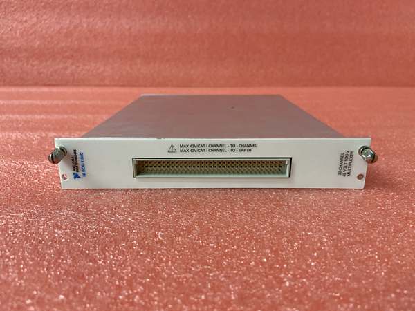
- Input Voltage Range: ±60 VDC, 30 VACrms, ±42 VACpeak
- Common-Mode Range: ±60 VDC with respect to CGND
- Input Impedance: >1 MΩ (powered on), 90 kΩ (powered off), 900 kΩ (overload)
- Gain Error: 0.02% of reading max (after calibration)
- Offset Error: 300 μV max (after calibration)
- Nonlinearity: 0.01% of full-scale range
- CMRR: 70 dB (50-60 Hz), 70 dB (DC)
- Output Range: ±10 V
- Output Impedance: 91 Ω
- Bandwidth: 10 kHz (-3 dB cutoff), three-pole low-pass filter
- Step Response: To 0.1% accuracy in 200 μs, to 0.01% accuracy in 1 ms
- Minimum Sample Interval: 3 μs (0.012% accuracy), 10 μs (0.0061% accuracy)
- System Noise: 500 μVrms (referenced to input)
- Digital I/O: Compatible with TTL levels (VIH ≥2 V, VIL ≤0.8 V)
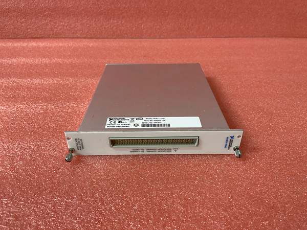
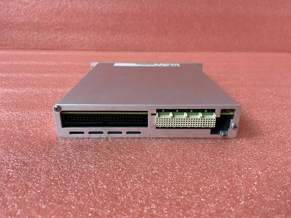
- Connectors: 50-pin male ribbon cable (rear), 96-pin male DIN C (front)
- Power Requirements: +5 V at 15 mA max, ±15 V at 150 mA max
- Operating Temperature: 0°C to 50°C (32°F to 122°F)
- Storage Temperature: -55°C to 150°C
- Relative Humidity: 5% to 90% non-condensing
- Dimensions: 11.5 × 27.3 cm (4.54 × 10.75 in.)
- Warm-up Time: 20 minutes recommended
- Calibration Interval: Annually or after operating outside 20-30°C range

NI SCXI-1104C
The Real-World Problem It Solves
When you need to measure multiple medium-voltage signals (up to ±60 V) and multiplex them into a single DAQ channel, this module provides signal conditioning, filtering, and protection in one package. The divide-by-10 attenuator extends the input range beyond standard ±10 V DAQ inputs while maintaining accuracy.
Where you’ll typically find it:
- Industrial process monitoring with multiple voltage transducers
- Power supply testing and validation
- Battery pack voltage monitoring
- Motor drive and inverter voltage measurements
- Automated test equipment for automotive or aerospace components
Bottom line: It converts 32 medium-voltage differential signals into conditioned, filtered outputs that safely interface with standard DAQ devices, reducing the need for external attenuators and protection circuits.
Hardware Architecture & Under-the-Hood Logic
The SCXI-1104C uses a multiplexed architecture where each of the 32 differential inputs passes through an attenuator stage, programmable amplifier, and three-pole low-pass filter before being routed to a single output channel. An analog multiplexer selects which channel appears at the output.
Signal flow and processing logic:
- Input Stage: Each differential input has a divide-by-10 attenuator for high-voltage measurements up to ±60 V.
- Protection Circuitry: Input protection prevents damage from overvoltage up to ±42 VACpeak or ±60 VDC.
- Programmable Amplifier: PGA adjusts gain to match input signal to the ±10 V output range.
- Low-Pass Filter: Three-pole filter with 10 kHz cutoff removes high-frequency noise and aliases.
- Analog Multiplexer: SCXI bus multiplexer selects one of 32 channels for the output.
- Output Stage: Single-ended ±10 V output with 91 Ω impedance drives the DAQ device input.
- Digital Control: Digital logic controls multiplexer addressing, gain settings, and calibration constants stored in EEPROM.
- Power Distribution: ±15 V and +5 V rails power the analog and digital circuitry respectively.
Field Service Pitfalls: What Rookies Get Wrong
Exceeding Input Voltage Limits
Techs assume the “medium voltage” label means the module can handle arbitrary high voltages. The maximum working voltage is ±60 VDC or ±42 VACpeak. Exceeding this damages input protection diodes.
- Field Rule: Always verify sensor output ranges before connecting. Use a multimeter to measure the maximum expected voltage under fault conditions. If you need to measure higher voltages, add external voltage dividers before the SCXI-1104C inputs.
Skipping Warm-up Time
The module requires 20 minutes of warm-up for optimal accuracy. Field technicians often start measurements immediately after power-up, resulting in drift and offset errors that look like sensor faults.
- Quick Fix: Power up the SCXI chassis at least 20 minutes before critical measurements. Record ambient temperature—if it’s outside the 20-30°C range, you’ll need to recalibrate before the next measurement run.
Calibration Drift After Temperature Excursions
The offset and gain temperature coefficients (50 μV/°C and 20 ppm/°C) apply outside the 15-35°C range. Field deployments in outdoor environments experience accuracy degradation without recalibration.
- Field Rule: If the module operates outside 15-35°C, recalibrate before critical measurements. Keep a calibration log documenting when temperature limits were exceeded and when recalibration was performed.
Overloading the Output Stage
The analog output is short-circuit protected but not overvoltage-protected. Applying external voltages to the output connector while the module is powered can damage output drivers.
- Quick Fix: Never connect external voltage sources to the SCXI-1104C output. If you need to monitor the output signal with another instrument, use a high-impedance differential probe—never connect ground-referenced equipment directly.
Incorrect Ground Reference Practices
Floating inputs or improper grounding creates ground loops that introduce noise into measurements. The common-mode range is ±60 VDC relative to CGND.
- Field Rule: Connect the sensor shield or reference ground to the chassis ground (CGND) terminal at a single point. Avoid creating multiple ground paths between the SCXI-1104C and the device under test. Use twisted-pair shielded cables for differential inputs.
Confusing SCXI-1104 vs. SCXI-1104C Filter Characteristics
The standard SCXI-1104 has a 2 Hz cutoff filter for 60 Hz noise rejection, while the SCXI-1104C has a 10 kHz cutoff for faster response. Using the wrong module for your application compromises either noise rejection or bandwidth.
- Field Rule: Verify your filter requirements before installation. If you need DC and near-DC measurements with maximum noise rejection, use SCXI-1104 (2 Hz filter). If you need faster dynamic measurements up to 10 kHz, use SCXI-1104C. Never substitute one for the other without confirming the bandwidth requirements.


