
Description
Hard-Numbers: Technical Specifications
- Counter/Timers: 8 channels, 32-bit resolution
- Maximum Source Frequency: 80 MHz (default PFI), 100 MHz (PXIe-DSTAR), 50 MHz (other PFI lines)
- Minimum Pulse Width: 6.25 ns (frequency measurement on PXIe-DSTAR), 20 ns (pulse/pulse-width measurements)
- Digital I/O: 40 PFI lines, TTL/CMOS compatible, individually programmable as input or output
- Output Current: ±6 mA per line
- Input Voltage Protection: -3 V to 8 V
- Output Impedance: 75 Ω
- Pull-Down Resistor: 51 kΩ
- OCXO Frequency: 10 MHz nominal
- OCXO Warm-Up Time: 5 minutes (to within 20 ppb of final frequency)
- OCXO Short-Term Stability: ±0.5 ppb per day (after 30 days operation)
- OCXO Long-Term Stability: ±50 ppb per year
- OCXO Temperature Drift: ±10 ppb (within operating temperature range)
- Base Clock Accuracy: ±10 ppb (temperature only), ±75 ppb (temperature + 1 year drift)
- Internal Timebases: 100 kHz, 20 MHz, 100 MHz
- External Timebases: 0 MHz to 25 MHz (standard), 0 MHz to 100 MHz (PXIe-DSTAR)
- PLL Frequency Locking: 10 MHz, 20 MHz, 100 MHz (PXIe_CLK100, PXIe-DSTAR, PXI_STAR)
- Counter FIFO: 127 samples per counter (dedicated DMA per counter)
- Waveform DIO FIFO: DO: 2,047 samples; DI: 255 samples
- DI/DO Sample Clock: 0 to 10 MHz (DMA, system dependent)
- Digital Line Filters: 90 ns, 5.12 µs, 2.56 ms, custom interval, disable
- Debounce Filter Settings: 90 ns, 5.12 µs, 2.56 ms, customer interval, disable
- Measurements Supported: Frequency, edge counting, pulse, pulse-width, semi-period, period, two-edge separation, encoder position (x1, x2, x4 quadrature)
- Output Applications: Pulse, pulse train with dynamic updates, frequency division, equivalent time sampling
- Bus Interface: PXI Express Gen 1 x1, single-slot
- Slot Compatibility: x1 and x4 PXI Express
- Power Consumption: +3.3 V @ 1.8 A (5.9 W), +12 V @ 1.325 A (15.9 W); total 21.8 W
- Operating Temperature: 0°C to 50°C
- Storage Temperature: -40°C to 71°C
- Weight: 180 g
- Calibration Interval: 2 years
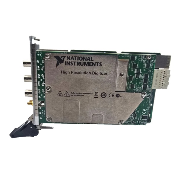
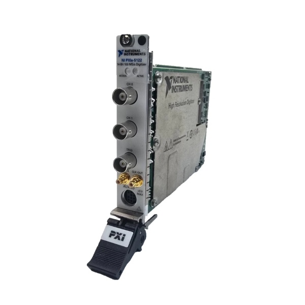
NI PXIe-5122 (779967-03)
The Real-World Problem It Solves
Standard PXI counter modules with TCXO references drift over hours, killing encoder position accuracy in long-duration motion control tests or frequency measurements spanning shifts. The PXIe-6614 packs an oven-controlled crystal oscillator (OCXO) with ±50 ppb/year stability in a single-slot PXIe module—your position measurements stay accurate from Monday morning to Friday afternoon without re-calibration.
Where you’ll typically find it:
- Automotive powertrain test cells counting crankshaft position sensor pulses over 24-hour durability cycles where ±50 ppb stability matters
- Semiconductor wafer prober timing synchronization where multiple chassis need a common 10 MHz reference with phase-lock capability
- Motion control systems measuring quadrature encoder position on CNC machines and robotic arms with microsecond-level accuracy
Bottom line: This counter module is your timing backbone for long-duration precision measurements—the OCXO keeps your timebase stable when other modules would have drifted out of spec, eliminating re-calibration downtime in extended test cycles.
Hardware Architecture & Under-the-Hood Logic
The PXIe-6614 is a x1 PXI Express module (21.8 W total draw: 5.9 W at +3.3 V, 15.9 W at +12 V) with an onboard oven-controlled crystal oscillator that outputs a 10 MHz reference. The OCXO feeds a phase-locked loop (PLL) that locks to external references (PXIe_CLK100, PXIe-DSTAR, PXI_STAR) at 10/20/100 MHz and generates internal 100 kHz, 20 MHz, and 100 MHz timebases distributed to 8 counter/timers and digital I/O subsystems. Each counter has a dedicated scatter-gather DMA controller with 127-sample FIFO—no shared DMA bottlenecks. The 40 PFI lines can serve as static DI/DO, timing inputs/outputs, or counter sources. The NI-STC3 timing chip provides advanced triggering and synchronization through the PXI trigger bus.
- OCXO warm-up: 5-minute warm-up brings 10 MHz crystal to within 20 ppb of final frequency; OCXO maintains temperature stability over operating range
- PLL lock: Phase-locked loop locks to external reference (PXIe_CLK100 @ 100 MHz, PXIe-DSTAR @ 10/20/100 MHz, PXI_STAR @ 10/20 MHz) or runs on internal OCXO
- Timebase distribution: PLL outputs 100 MHz to timebase dividers generating 100 kHz, 20 MHz, and 100 MHz internal timebases for counters and DIO
- Counter operation: 8 counters receive timebase from PLL; each counter has dedicated DMA controller and 127-sample FIFO for buffered acquisition/generation
- Counter measurement mode: Counter counts edges on Source input (up to 80 MHz default PFI, 100 MHz PXIe-DSTAR) with optional prescaling (2x, 8x); Gate input controls counting window
- Encoder position mode: A/B/Z inputs support x1/x2/x4 quadrature decoding with Channel Z index reloading for position reset
- Pulse measurement mode: Counter measures pulse width, period, semi-period, or two-edge separation with 20 ns minimum pulse width (6.25 ns on PXIe-DSTAR for frequency measurement)
- Digital I/O operation: 40 PFI lines operate as static DI/DO or waveform DIO; DI/DO sample clock at 0-10 MHz with DMA transfer to host PC
- Debounce filtering: Programmable digital filters (90 ns to 2.56 ms or custom) clean noisy encoder/sensor inputs before counter measurement
- Trigger routing: PXI trigger bus routes start, pause, reference triggers to counters and DIO; NI-Sync API handles device-to-device synchronization across chassis
Field Service Pitfalls: What Rookies Get Wrong
Insufficient OCXO Warm-Up Before Critical Measurements
Technicians power on the chassis and immediately start long-duration frequency counting or encoder position measurements without letting the OCXO stabilize. The 10 MHz crystal requires 5 minutes to reach within 20 ppb of final frequency; measurements taken during warm-up drift as the oven heats the crystal.
- Field Rule: Power on the chassis 10 minutes before critical measurements. The OCXO needs 5 minutes to hit 20 ppb stability, but add margin for ambient temperature equilibrium. For maximum accuracy over hours, let it run 30 minutes before the test. Remember: OCXO is an oven—it needs time to heat up.
Ignoring OCXO Retrace Error After Power Cycling
Engineers power cycle the PXIe-6614 mid-test and assume frequency stability returns instantly. OCXO retrace error is ±10 ppb—the crystal “remembers” its previous frequency and drifts back to setpoint over time. Your long-duration measurements take a hit every power cycle.
- Field Rule: Avoid power cycling the PXIe-6614 during critical test sequences. If power cycling is unavoidable, add 30 minutes warm-up after retrace. For multi-shift tests, keep chassis powered continuously—OCXO drift (±50 ppb/year) is better than retrace (±10 ppb) per cycle.
Using PFI Lines Beyond Voltage Protection Limits
Field techs connect 24 V sensor outputs directly to PFI inputs assuming “TTL/CMOS compatible” means robust. Input voltage protection is -3 V to 8 V. Exceeding this range fries the input buffer—no fuse, no graceful failure.
- Field Rule: Never exceed -3 V to 8 V on PFI inputs. Use external voltage dividers or level shifters for 12 V/24 V sensors. Verify sensor output levels with a scope before connecting to PXIe-6614. Input protection is a specification, not a design target—abusing it kills the module.
Incorrect Debounce Filter Selection for Encoder Speed
Rookies use 5.12 µs debounce filter on high-speed encoders (10,000 PPR at 3000 RPM). Minimum edge spacing is 2 µs—filter swallows edges, counter miscounts position, test fails with “encoder error” flags.
- Quick Fix: Calculate encoder edge period: Period (s) = 60 / (RPM × PPR × 4). For 10,000 PPR at 3000 RPM, edges are 0.5 µs apart—use 90 ns filter or disable. Rule of thumb: debounce filter < 50% of minimum edge spacing. Disable filter for max encoder speed; enable only for noisy signals.
Forgetting Prescaling for High-Frequency Edge Counting
Users configure edge counting on a 64 MHz signal without prescaling and get garbage counts. Maximum source frequency without prescaling is 25 MHz (50 MHz on default PFI lines). The counter cannot resolve faster edges.
- Field Rule: For frequencies above 25 MHz, enable 2x or 8x prescaling. 2x prescaling handles up to 50 MHz; 8x handles up to 80 MHz (100 MHz on PXIe-DSTAR). Remember: prescaling divides frequency—your count value is prescaled by the same factor. Account for this in post-processing.
Leaving Pull-Down Resistor Configuration Default for Open-Collector Outputs
Technicians connect open-collector encoder outputs to PFI inputs without checking pull-down resistor defaults. PFI lines have 51 kΩ pull-down—weak for long cable runs with high capacitance, causing slow rise times and edge jitter.
- Quick Fix: Use external 4.7 kΩ pull-up resistors to +5 V for open-collector outputs on cables >3 meters. Verify rise time at the PXIe-6614 input with a scope—target <10 µs. Long cables need stronger pull-ups; default 51 kΩ is for short runs or CMOS outputs.
Overloading PFI Output Current Limits
Engineers drive multiple external inputs from a single PFI output configured as timing signal. PFI output current is ±6 mA. Driving three 50 Ω loads draws 24 mA—output sags, timing jitter increases, downstream modules miss triggers.
- Field Rule: Total sink/source current per PFI line must be ≤6 mA. For fan-out to multiple modules, use external buffer (74HC125 or similar) or PXI trigger bus (higher drive capability). Calculate total load current: I = V/R × number-of-loads. If >6 mA, buffer it.
Commercial Availability & Pricing Note
Please note: The listed price is for reference only and is not binding. Final pricing and terms are subject to negotiation based on current market conditions and availability.


