
Description
Hard-Numbers: Technical Specifications
-
Channels: 4 independent SMU channels per module
-
Voltage Range: ±24 V DC (programmable, 4-quadrant operation)
-
Current Range: ±150 mA per channel (±600 mA aggregate, pulsed to 500 mA)
-
Power: 6 W max per channel (24W total, DC or pulsed)
-
Measurement Resolution: Voltage: 100 nV (20-bit ADC), Current: 10 fA (20-bit ADC)
-
Source Resolution: Voltage: 100 µV, Current: 10 pA
-
Update Rate: 500 kS/s per channel (sampling), 100 µs settling to 0.1% (typical)
-
Output Impedance: <10 mΩ in voltage source mode (low-noise design)
-
Isolation: Channel-to-channel: 250 V DC, Channel-to-earth: 250 V DC (CAT I)
-
Operating Temperature: 0°C to +55°C (calibrated), -20°C to +70°C (storage)
-
Power Draw: 45W max from PXIe chassis (3.3V/12V rails)
-
Connectivity: 9-pin D-sub per channel (front panel), shielded twisted pair recommended
-
Dimensions: 3U x 160mm (PXI Express, x4 PCIe Gen2 interface)
The Real-World Problem It Solves
Benchtop SMUs are precise but slow—one channel, one DUT, manual cable swaps. Production floors need parallel test with Keithley 2400-grade accuracy at four times the density. The PXIe-4145 packs four independent source-measure channels into one PXI slot, each with its own DAC, ADC, and force/sense circuitry. No relay switching, no settling time between channels, no rack full of boxes.
Where you’ll typically find it:
-
Power semiconductor wafer probe: Simultaneous gate leakage, RDS(on), and breakdown tests on MOSFETs—four sites in parallel cuts test time 75%.
-
LED/OLED binning: Forward voltage and reverse leakage at 100 µs per point; 500 kS/s catches thermal drift during pulse tests.
-
MEMS sensor calibration: High-impedance leakage measurements (femtoamp resolution) on capacitive pressure sensors while sourcing excitation voltage.
Bottom line: It replaces four box SMUs with one PXI slot, synchronized by chassis backplane trigger lines, not GPIB spaghetti.

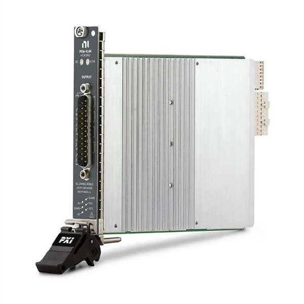
NI PXIE-4145
Hardware Architecture & Under-the-Hood Logic
Each channel is a complete source-measure loop: 20-bit DAC sets force value, force amplifier drives DUT, separate sense amplifier measures actual voltage/current, 20-bit ADC digitizes result. All four channels run independently—no multiplexers, no shared resources. The PXIe interface streams data to host memory at 500 kS/s per channel without CPU intervention.
-
Force path: DAC output → force amplifier → DUT via Force HI/LO terminals. Amplifier operates in voltage or current priority mode (user-selectable).
-
Sense path: Kelvin (4-wire) sense lines → differential amplifier → 20-bit sigma-delta ADC. Separate ADC for voltage and current measurement on each channel.
-
Limit/compliance: Hardware comparators clamp output if DUT draws over current limit or voltage compliance—protects DUT and module, response time <10 µs.
-
PXIe integration: x4 PCIe Gen2 link to chassis controller; DMA engine streams measurement buffers. PXI Trigger bus (0-7) synchronizes multiple SMUs or DUT stimulus.
-
Guard/shield: Active guard drives cable shield to common-mode voltage—eliminates leakage in fA measurements. Critical for high-impedance work.
Field Service Pitfalls: What Rookies Get Wrong
Ignoring Kelvin (4-Wire) Connections
The front panel has Force and Sense pins for each channel. Using only Force (2-wire) adds lead resistance to voltage measurements—0.1Ω of cable becomes 10 mV error at 100 mA, killing precision on low-voltage device tests.
-
Field Rule: Always connect Sense HI/LO at the DUT terminals, never at the cable end. Use twisted pair for Force, separate twisted pair for Sense. If you must run 2-wire (prober limitations), null out lead resistance with offset compensation in software—but know you’re throwing away accuracy.
Floating Channels Without Isolation Awareness
Channel-to-channel isolation is 250V, but that’s DC working voltage, not transient rating. Connecting Channel 1 to a 200V MOSFET drain and Channel 2 to a 5V gate driver without common reference invites ground loops and slew-rate induced crosstalk.
-
Quick Fix: Tie all channel LOs to a single chassis ground point when testing floating DUTs. For high-side switching tests, use isolated channel mode but verify common-mode voltage limits (±250V max). Watch for capacitive coupling between channels during fast edges—500V/µs slews on one channel injects noise into adjacent channels. Add 10nF ceramic caps at DUT terminals if needed.
Overlooking Thermal Derating
Six watts per channel sounds generous until you’re sinking current into a shorted power FET at 24V. The PXIe chassis cooling must handle 45W from one slot, and internal channel temperature sensors throttle output if the heat sink hits 85°C.
-
Field Rule: Monitor “Channel Temperature” in NI-DMM or LabVIEW. If you’re running continuous 6W per channel, verify chassis fan speed and slot airflow. Pulsed operation (duty cycle <10%) extends thermal headroom—use pulsed mode for high-power stress tests. Never block the module’s top or bottom vents; conduction-cooled PXI chassis need special thermal interfaces for high-dissipation SMUs.


