
Description
Hard-Numbers: Technical Specifications
- Total Slots: 18 slots (1 system controller slot, 17 hybrid peripheral slots)
- Slot Type: 17 hybrid slots (PXI, PXIe, cPCI, cPCIe compatible)
- System Bandwidth: 4 GB/s (PCI Express Gen 1/2 switch fabric)
- Per-Slot Bandwidth: 500 MB/s (PCI Express x1 per slot)
- Slot Cooling Capacity: 58 W per slot (650W total system power for >38W modules, 800W total chassis power)
- Operating Temperature: 0°C to 50°C (standard), 0°C to 40°C (any module >38W)
- Operating Humidity: 10% to 90% RH, noncondensing
- Power Input: 90-264 VAC, 47-440 Hz
- Power Supply: 800 W instrument-grade, single (non-redundant), field-replaceable from rear
- System Clock: VCXO (Voltage Controlled Crystal Oscillator), ±25 ppm accuracy over temperature range
- 10 MHz Clock: PXI_CLK10, ±25 ppm, 5 ps RMS jitter (10 Hz–1 MHz), 250 ps slot-to-slot skew
- 100 MHz Clock: PXIe_CLK100/PXIe_SYNC100, ±25 ppm, 2 ps RMS jitter (12 kHz–20 MHz), 100 ps slot-to-slot skew
- Trigger Bus: PXI Trigger Bus (8 TTL lines), PXIe Differential Star Triggers (timing/sync option)
- Acoustics: 34.4 dBA at 0-30°C (Auto fan, 38W profile), 55 dBA (High fan)
- Fan Modes: Auto (temperature-controlled), High (fixed high-speed)
- Dimensions: 177.1 mm H × 445.5 mm W × 463.6 mm D (6.97″ × 17.54″ × 18.25″)
- Weight: 13.5 kg (29.8 lb)
- Rack Mount: 3U standard, front/rear mounting options with M4 tapped holes
- Monitoring: Voltage rails, fan speed, chassis temperature (accessible via NI MAX and System Configuration API)
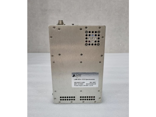
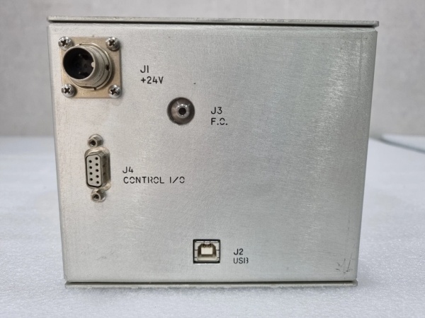
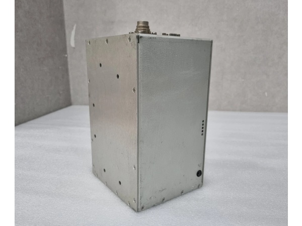
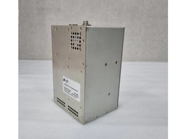
LAM 685-064724-002
The Real-World Problem It Solves
Traditional PXI chassis force you to choose between PXI and PXIe slots, then hit thermal limits when stuffing high-power RF modules into compact racks. The PXIe-1084 packs 17 hybrid slots into a single 3U frame—any slot takes PXI, PXIe, or legacy cPCI modules—while delivering 58W per-slot cooling and running quiet (34.4 dBA) on the production floor. No more slot shuffling or overheated cabinets when mixing legacy PXI DAQ with high-bandwidth PXIe digitizers.
Where you’ll typically find it:
- Automotive ECU test rigs: Hybrid PXI/PXIe modules共存—legacy PXI CAN interfaces alongside PXIe RF vector signal transceivers in HIL simulators
- Semiconductor ATE systems: High-density digital I/O and SMU modules (58W cooling) sharing chassis with PXIe source measure units in production test
- Aerospace/defense test bays: Rack-mounted PXIe-1084s running 24/7 with mixed PXI/PXIe instrumentation—requiring quiet operation (34.4 dBA) near operators and field-replaceable fans/power supplies without de-racking
Bottom line: This chassis eliminates the slot-type bottleneck and thermal runaway in high-density mixed-technology PXI systems by giving you 17 hybrid slots with 58W cooling and sub-35 dBA noise in a single 3U rack unit.
Hardware Architecture & Under-the-Hood Logic
The PXIe-1084 is a 3U 19-inch rack-mount chassis with an all-hybrid backplane supporting PXI, PXI Express, CompactPCI, and CompactPCI Express signaling. The backplane uses PCI Express Gen 1/2 switching fabric with 24 total lanes (4 GB/s system bandwidth), distributing 500 MB/s per slot to 17 peripheral slots via x1 PCI Express lanes per hybrid slot. A VCXO-based clock generator provides 10 MHz (PXI_CLK10) and 100 MHz (PXIe_CLK100, PXIe_SYNC100) system reference clocks distributed to all slots with minimal jitter (5 ps RMS for 10 MHz, 2 ps RMS for 100 MHz) and slot-to-slot skew (250 ps for 10 MHz, 100 ps for 100 MHz). The timing and synchronization option (786397-01) adds external 10 MHz reference in/out SMA connectors, remote inhibit, fault monitoring, and differential star triggers for multi-chassis synchronization. An 800 W instrument-grade power supply delivers +5V, +3.3V, +12V, -12V rails to the backplane with remote voltage sensing for load regulation, while dedicated 12V fan power rail isolates cooling noise from measurement rails. Four PWM-controlled fans provide 58W per-slot cooling with Auto (temperature-adaptive) and High (fixed) modes, monitored by internal sensors accessible via NI MAX or System Configuration API.
- AC power (90-264 VAC, 47-440 Hz) enters → instrument-grade 800W PSU converts to DC rails (+5V, +3.3V, +12V, -12V) with remote sensing to compensate for backplane voltage drop under load
- Power rails routed to hybrid backplane → each of 17 peripheral slots receives PXIe signaling (x1 PCIe Gen1/2, 500 MB/s), PXI signaling (132 MB/s), 10 MHz clock (PXI_CLK10), 100 MHz differential clock (PXIe_CLK100/PXIe_SYNC100), and PXI trigger bus lines (8 TTL triggers)
- VCXO clock generator distributes 10 MHz (±25 ppm, 5 ps RMS jitter) and 100 MHz (±25 ppm, 2 ps RMS jitter) reference clocks to all slots with minimal slot-to-slot skew (250 ps for 10 MHz, 100 ps for 100 MHz)
- System controller inserted in Slot 0 → acts as PXIe embedded controller, managing backplane communication, routing triggers, and accessing chassis monitoring data (voltage rails, fan speeds, temperatures) via System Configuration API
- Peripheral modules inserted in hybrid slots 1-17 → hybrid connector provides both PXI and PXIe signaling; module auto-negotiates bus type based on connector keying (PXI modules use PXI pins 1-110, PXIe modules use PXIe pins 111-156)
- Thermal sensors (air inlet temperature, internal chassis temperature) monitor heat load → PWM fans adjust speed in Auto mode to maintain 38W or 58W per-slot cooling profiles; High mode locks fans at maximum RPM for worst-case thermal conditions
- Timing/sync option enables external 10 MHz reference input via rear SMA connector → backplane PLL phase-locks internal 10/100 MHz clocks to external reference for multi-chassis synchronization; external 10 MHz reference out allows daisy-chaining chassis clocks
- Trigger routing managed by NI MAX → PXI trigger bus (8 TTL lines) and PXIe differential star triggers (timing/sync option) routed between slots and to external SMB connectors for device synchronization; reservation prevents double-driving
- Chassis monitoring accessed via NI MAX or System Configuration API → real-time voltage rail readings, fan RPM, temperature readings, fault status displayed; remote inhibit signal (timing/sync option) allows external chassis power control
- Cooling optimization → dedicated 12V fan power rail isolated from backplane measurement rails prevents fan motor noise coupling into PXI/PXIe module power; PWM fan control enables wider RPM range for acoustic optimization (34.4 dBA at 0-30°C, 38W profile)
LAM 685-064724-002
Field Service Pitfalls: What Rookies Get Wrong
Overlooking Hybrid Slot Power Budget When Mixing PXI and PXIe Modules
Rookies assume all 17 hybrid slots deliver full 58W cooling regardless of module type, ignoring thermal derating rules. PXIe-1084 provides 800W total chassis power—enough for 16 slots at 38W each or 13 slots at 58W each, not 17 slots at 58W simultaneously. Mixing high-power PXIe RF modules (58W) with legacy PXI DAQ modules (typically <20W) in all slots exceeds total power budget, triggering thermal shutdown or voltage rail sag.
Field Rule: Calculate total system power: Σ(module power) + ~200W chassis overhead ≤ 800W. Verify each module’s power dissipation from its datasheet. If you’re installing >13 modules at 58W each, you’re exceeding budget—move high-power modules to chassis with higher capacity (PXIe-1095: 82W/slot, 2400W total) or derate to 38W modules. Use NI MAX’s chassis monitoring tab to watch voltage rails during startup—any rail dropping >5% from nominal indicates overcurrent.
Ignoring Operating Temperature Limits for High-Power Modules
Techs install PXIe-1084 in hot cabinets (>40°C ambient) with modules requiring >38W cooling, ignoring the 0-40°C temperature limit for >38W modules. At 40-50°C ambient, the chassis can only dissipate 38W per slot; >58W modules will overheat, trigger thermal protection, or fail prematurely. The datasheet explicitly states: “Any module requires >38W cooling capacity per slot | 0-40°C.”
Quick Fix: Measure cabinet ambient temperature at the chassis air inlet with a calibrated thermometer. If >40°C ambient and you’re using >38W modules, either upgrade cabinet cooling, relocate chassis to cooler environment, or derate to modules requiring ≤38W cooling. For hot environments (40-50°C ambient), PXIe-1084 supports only ≤38W modules—confirm module power specs before installation.
Misconfiguring Fan Mode and Overriding Thermal Management
Engineers set fan mode to High for “maximum cooling” permanently, ignoring acoustic and wear implications. High mode locks fans at max RPM (~55 dBA), increasing fan wear and causing operator fatigue in quiet labs or production floors. Auto mode adjusts fan speed based on air inlet temperature (34.4 dBA at 0-30°C), providing sufficient cooling while minimizing noise and extending fan life.
Field Rule: Leave fan mode in Auto for normal operation; switch to High only during commissioning with full module load or troubleshooting thermal issues. Monitor chassis inlet temperature in NI MAX—if consistently <30°C, Auto mode provides adequate cooling. Remember: High mode is for worst-case thermal conditions, not everyday use—constant max RPM reduces fan MTBF from ~50,000 hours to <20,000 hours.
Forgetting External 10 MHz Reference Impedance Matching
Technicians connect external 10 MHz reference clock to the timing/sync option SMA connector without verifying impedance, causing clock signal degradation or PLL unlock. The PXIe-1084’s external 10 MHz Ref In expects 50 Ω ±5 Ω input impedance; mismatched cables or unterminated lines introduce reflections, increasing jitter beyond 1 ps RMS specification.
Quick Fix: Use 50 Ω coaxial cable (RG-58/U or equivalent) with SMA-to-SMA connectors for external 10 MHz reference. Verify output impedance of external clock source is 50 Ω ±5 Ω. Check NI MAX chassis monitoring page for “External 10 MHz Lock Status”—if not locked, check cable continuity and impedance with a VNA or TDR. For daisy-chained chassis, terminate the final SMA connector with 50 Ω terminator.
Neglecting Slot Blocker Installation When Running Partial Loads
Rockets leave empty slots uncovered when chassis isn’t fully populated, causing airflow bypass and hotspots behind populated modules. Unblocked empty slots let intake air bypass filter and flow directly out exhaust, reducing cooling efficiency for populated slots by up to 30% and increasing module temperatures unnecessarily.
Field Rule: Install NI slot blockers (filler panels) in all empty peripheral slots. Slot blockers ensure airflow is forced through populated modules, maintaining 58W per-slot cooling capacity. Order slot blockers (NI part varies by chassis) with initial chassis purchase or as spare—field replacement takes <5 minutes per slot. For permanent partial-load configurations, blocked slots improve thermal uniformity and reduce fan RPM in Auto mode.
Assuming Timing/Sync Option Included in Base Part Number (784058-01)
Engineers order PXIe-1084 expecting external 10 MHz reference in/out SMA connectors, remote inhibit, and fault monitoring, but receive base part number 784058-01 (no timing/sync). The 786397-01 variant includes the timing and synchronization option; 784058-01 is standard chassis with no external clock routing beyond internal distribution.
Field Rule: Verify part number before ordering: 784058-01 (standard, VCXO clock only), 786397-01 (with timing/sync option: external 10 MHz REF in/out SMA, remote inhibit, fault monitoring, differential star triggers). If you need multi-chassis synchronization or external clock input, specify 786397-01. Timing/sync option is factory-installed—cannot be retrofitted in the field. Use NI MAX’s chassis identification dialog to confirm option presence (timing/sync chassis show additional SMA connectors on rear panel).
Commercial Availability & Pricing Note
Please note: The listed price is for reference only and is not binding. Final pricing and terms are subject to negotiation based on current market conditions and availability.


