
Description
Hard-Numbers: Technical Specifications
- Protocol Support: CAN 2.0A/B, CAN FD
- Port Count: 2 ports (independent software-selectable physical layers)
- High-Speed/FD Baud Rate: 40 kbps to 1 Mbps (CAN 2.0B); up to 5 Mbps certified CAN FD (TJA1043), up to 8 Mbps experimental
- Low-Speed/Fault-Tolerant Baud Rate: 40 kbps to 125 kbps
- Single-Wire Baud Rate: 33.3 kbps to 83.3 kbps (requires 8-18 V bus power)
- Operating Temperature: 0°C to 55°C
- Isolation Rating: 500 Vrms withstand (5-second dielectric test); 60 VDC continuous, Measurement Category I, port-to-port and port-to-earth ground
- Power Draw: +5 VDC at 640 mA, +3.3 VDC at 940 mA (typical)
- Hardware-Accelerated Frames: Up to 192 frames per port
- Timestamp Resolution: 1 μs
- Bus Line Voltage Range: -27 VDC to +40 VDC (CAN_H, CAN_L)
- Trigger Lines: 7 TTL input/output
- Clock Lines: 1 TTL input/output
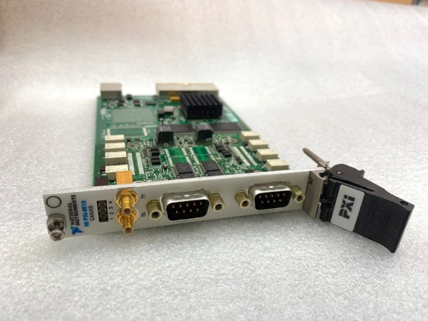
- I/O Connector: 9-pin male D-SUB per port
- Sync Connectors: 2 SMB front-panel sync connectors
- Dimensions: 10.67 cm × 16.76 cm (4.2 in. × 6.6 in.)
- Weight: 102 g (3.6 oz)
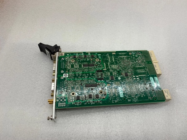
NI PXI-8513
The Real-World Problem It Solves
Traditional CAN interfaces lock you into one physical layer or require swapping cards when your test coverage expands across different vehicle networks. The PXI-8513 packs three CAN transceiver types—High-Speed/FD, Low-Speed/Fault-Tolerant, and Single-Wire—into a single 3U PXI slot, letting you switch protocols in software without touching the hardware. This means one card handles powertrain high-speed buses, body control low-speed networks, and OBD-II single-wire diagnostics, all synchronized with microsecond timing.
Where you’ll typically find it:
- Automotive HIL test rigs: Simulating mixed CAN networks (powertrain HS-CAN, chassis LS-FT-CAN, diagnostics SW-CAN) on ECUs during software validation
- Vehicle network monitoring: Recording multiple CAN buses simultaneously during road tests or on-vehicle diagnostics with time-synchronized data
- ECU production test: End-of-line testers communicating with modules using different CAN physical layers without requiring multiple interface cards
Bottom line: This card eliminates the multi-card protocol mismatch problem by putting three transceivers and hardware acceleration in one slot, saving rack space and reducing configuration errors when you need full-coverage CAN testing.
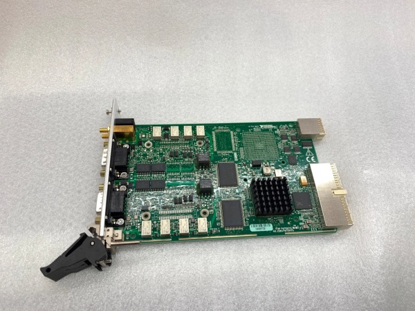
Hardware Architecture & Under-the-Hood Logic
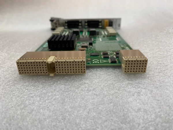
The PXI-8513 is a PXI module with two independent CAN ports, each featuring its own dedicated processor and onboard transceiver bank (TJA1041/TJA1043 for HS/FD, TJA1054A/TJA1055T for LS/FT, AU5790/NCV7356 for Single-Wire). The per-port processors manage up to 192 hardware-accelerated frames, handling repetitive frame matching and signal translation without CPU intervention, while the NI-XNET device-driven DMA engine moves data between the module and host memory via the PXI backplane at microsecond latency. Ports are isolated from each other and earth ground at 60 VDC continuous (500 Vrms withstand) to prevent ground loops, and the module exposes 7 TTL trigger lines and 1 TTL clock line for hardware-timed synchronization with other PXI instruments.
- Host software sends configuration command via NI-XNET API specifying port, physical layer (HS/FD, LS/FT, SW), baud rate, and signal database (.DBC, FIBEX, .NCD) for frame-to-signal translation
- Per-port processor validates configuration and enables selected onboard transceiver (e.g., TJA1043 for HS/FD at 5 Mbps CAN FD) while disabling unused transceivers to save power
- DMA engine allocates circular buffer in host memory for high-throughput streaming, eliminating per-frame CPU interrupts during receive/transmit operations
- CAN frames arrive from bus → transceiver converts differential signals to logic levels → onboard processor filters and routes frames matching hardware-accelerated list directly to DMA buffer without host CPU involvement
- Non-accelerated frames processed by host CPU via NI-XNET API calls (e.g.,
XNET Read.vi) using software polling for flexibility but higher latency - Timestamp counter (1 μs resolution) stamps each received/transmitted frame, synchronized to PXI 10 MHz clock or external timebase via SMB sync connectors
- Trigger events (rising edge on TTL lines) can start/终止 frame logging or initiate transmission sequences, coordinated with other PXI modules via PXI trigger bus
- Hardware acceleration for signals extracts individual signal values from frames using signal database, converting raw CAN payload to engineering units automatically on the per-port processor
- Fault detection (bus-off, error passive, TX/RX error counters) monitored by transceiver and reported to host via NI-XNET status attributes; module automatically attempts bus recovery when error conditions clear
- Single-wire mode requires 8-18 V on bus power pin (pin 9 of D-SUB) to power the NCV7356 transceiver; without external V+, SW-CAN communication fails

NI PXI-8513
Field Service Pitfalls: What Rookies Get Wrong
Mixing CAN FD Speed Claims with Transceiver Revisions
Rookies assume any PXI-8513 supports 8 Mbps CAN FD out of the box, ignoring hardware revision dependencies. Early revisions (A-F) use TJA1041 transceivers limited to 1 Mbps; revision G+ uses TJA1043 certified for 5 Mbps CAN FD, with 8 Mbps being experimental and uncertified. Configuring 8 Mbps on older revisions yields garbage frames or driver warnings.
Field Rule: Check the green label on the PCB backside for format
19xxxx<rev>-4xL—revision G or later is required for >5 Mbps CAN FD. In NI MAX, verify the transceiver type under “Device Interfaces” and set CAN FD speed within the certified range for your hardware revision.Forgetting Single-Wire Bus Power on SW-CAN Applications
Techs connect SW-CAN pins (pin 1 for data, pin 9 for V+) but omit the 8-18 V external power source on pin 9. The NCV7356 single-wire transceiver requires this voltage to bias the bus; without it, the port won’t transmit or receive SW-CAN messages, and you’ll see “bus-off” errors or silent failure.
Quick Fix: Confirm pin 9 of the D-SUB connector receives 8-18 V from the vehicle OBD-II port or external supply. Use a multimeter to verify V+ presence before commissioning SW-CAN communication; NI-XNET reports “Transceiver Error” if bus power is missing during SW-CAN operation.
Overloading Hardware-Accelerated Frame Limit and Killing Real-Time Performance
Engineers configure hundreds of CAN frames for HIL testing without checking the 192-frame hardware-accelerated limit per port. Once exceeded, excess frames fall back to software processing on the host CPU, increasing latency from microseconds to milliseconds and causing frame drops at high bus loads (>80% CAN bandwidth utilization).
Field Rule: In NI-XNET Database Editor, prioritize critical cyclical frames (e.g., ECU torque commands at 10 ms) for hardware acceleration. Use the
XNET Session mode with HardwareTiming property set to True for these frames. Monitor host CPU utilization—if spikes above 80% during HIL runs, you’ve exceeded the acceleration budget and need to split traffic across multiple ports or modules.Ignoring Port Isolation Limits and Creating Ground Loops
Technicians treat the 60 VDC port isolation as carte blanche to connect arbitrary ground-referenced networks. Port isolation prevents ground loops between CAN buses at different potentials, but it doesn’t permit arbitrary voltage stacking—connecting a +24 V referenced CAN network to a port already biased at +5 V via another ground path can exceed the 60 VDC rating and blow isolation barriers.
Field Rule: Measure ground potentials between CAN networks before interconnecting ports. Verify each port’s COM pin (pin 3 or 5 on D-SUB) doesn’t exceed 60 VDC relative to earth ground when connected to your system. Use differential probes for bus monitoring on isolated ports, and never cascade ports to achieve voltages beyond the 60 VDC continuous rating.
Misconfiguring Termination and Ruining Bus Integrity
Rookies rely on software-enabled termination in NI-XNET but forget that both ports share the same termination setting—enabling 120 Ω on Port A also enables 120 Ω on Port B. This causes double-termination on a bus with multiple devices (e.g., 60 Ω equivalent), leading to signal reflections and corrupted frames.
Quick Fix: In NI MAX or NI-XNET properties, verify termination is disabled on ports monitoring existing buses (which already have ECU terminators). Only enable termination on the end-point ports of your test setup. For custom wiring, add external termination resistors manually and leave software termination disabled to avoid double-terminating the bus.
Commercial Availability & Pricing Note
Please note: The listed price is for reference only and is not binding. Final pricing and terms are subject to negotiation based on current market conditions and availability.


