

Description
Hard-Numbers: Technical Specifications
- Axis Count: 4 independent or coordinated axes
- Motor Types: Stepper or servo (closed-loop)
- Servo Update Rate: 62.5 to 500 μs/sample (62.5 μs max per axis)
- Encoder Input Rate: Up to 20 MHz quadrature encoder
- Stepper Pulse Rate: Up to 4 MHz
- Analog Outputs (Servo) : 4 channels, 16-bit, ±10 V range
- Analog Inputs: 8 multiplexed channels, 12-bit, ±10 V/±5 V/0-10 V/0-5 V ranges
- Digital I/O: 32 bits configured as 4 × 8-bit ports (0 to 5 V)
- Onboard Programs: Up to 10 concurrent motion programs
- Motion Modes: Point-to-point, linear, circular, vector-space, gearing, contouring
- I/O Connectors: Two 68-pin female VHDCI (Motion I/O + Digital I/O)
- RTSI Support: Yes (for multi-device synchronization)
- Operating Temperature: 0°C to 55°C (32°F to 131°F)
- Power Consumption: 5.7 W maximum (+5 V @ 1 A, +12 V @ 30 mA, –12 V @ 30 mA)

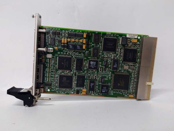
NI PXI-7344
The Real-World Problem It Solves
When you need multi-axis coordinated motion with real-time performance without tying up your host PC, this module handles trajectory generation and servo loops independently. The dual-processor architecture with embedded RTOS keeps motors running smoothly even when your Windows host hiccups.
Where you’ll typically find it:
- Semiconductor test handlers and wafer probers requiring precise multi-axis positioning
- Automated assembly systems with pick-and-place robots
- CNC retrofit projects needing flexible motion control
- Coordinate measuring machines (CMM) and precision stages
Bottom line: It delivers industrial-grade multi-axis motion control with real-time determinism, freeing your host application from time-critical servo loops.
Hardware Architecture & Under-the-Hood Logic
The PXI-7344 uses a dual-processor architecture with a dedicated motion DSP and a communications CPU. An embedded real-time operating system handles trajectory generation, servo loop execution, and program scheduling independently of the host PC.
Signal flow and processing logic:
- Host Communication: Host PC sends motion commands via PXI bus to communications CPU.
- Trajectory Generation: Motion DSP calculates position, velocity, and acceleration profiles.
- Servo Loop Execution: PID/PIVff servo algorithms run at 62.5 μs update rate.
- Stepper Output: Step/Dir signals drive stepper drives at up to 4 MHz pulse rate.
- Servo Output: 16-bit DAC outputs generate ±10 V command signals for servo amplifiers.
- Encoder Feedback: Quadrature encoder inputs (up to 20 MHz) close the position loop.
- Limit/Home Monitoring: Digital inputs monitor forward/reverse limits and home switches.
- Inhibit Control: Open-collector outputs enable/disable motor drives safely.
- RTSI Synchronization: Optional RTSI bus shares timing with DAQ and IMAQ modules.
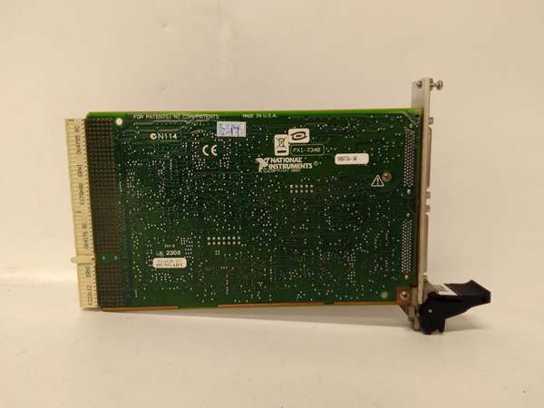
NI PXI-7344
Field Service Pitfalls: What Rookies Get Wrong
Wrong Ground Reference for Analog Signals
Engineers tie analog output ground to digital ground or chassis ground, creating ground loops that introduce noise into servo command signals. This causes jitter or oscillation in closed-loop systems.
- Field Rule: Use the dedicated Analog Output Ground pin for servo command signals. Never share this reference with digital I/O ground or chassis ground. Keep analog and digital ground returns separate all the way to the servo amplifier.
Ignoring Shutdown Input Wiring
The shutdown input disables all axes and command outputs, but techs often leave it floating or unconnected. An open shutdown input can cause erratic behavior if noise triggers it inadvertently.
- Quick Fix: Wire the shutdown input to your E-终止 circuit with a pull-up or pull-down resistor as specified in the manual. Test it by triggering the shutdown input and verifying all motor drives disable immediately.
Overloading the +5 V Host Supply
The module draws up to 1 A from the PXI +5 V rail. Adding too many peripherals or connecting high-current loads to the +5 V output on the motion I/O connector starves the module and causes brownouts.
- Field Rule: Never power external devices from the +5 V pin on the motion I/O connector—it’s meant only for encoders. Use an external power supply for peripherals. If the module resets intermittently under load, check your +5 V rail current.
Incorrect Encoder Wiring Phasing
Quadrature encoders need correct A/B phase relationship for proper direction detection. Reversed phases cause the motor to run backward when commanded forward, triggering limit switches.
- Field Rule: Verify encoder phasing using an oscilloscope before commissioning. Channel A should lead Channel B by 90 electrical degrees when rotating forward. If direction is wrong, swap A and B leads at the connector.


