
Description
Hard-Numbers: Technical Specifications
- Topology: 6×1 terminated multiplexer (SP6T)
- Frequency Range: DC to 26.5 GHz
- Characteristic Impedance: 50 Ω nominal
- Insertion Loss: <0.2 dB @ ≤3 GHz, <0.7 dB @ 26.5 GHz (warranted)
- VSWR: <1.2 @ ≤3 GHz, <1.7 @ 26.5 GHz (warranted)
- Open Channel Isolation: >80 dB @ ≤3 GHz, >55 dB @ 26.5 GHz (warranted)
- Maximum RF Carry Power: 150 W @ ≤3 GHz, 25 W @ 26.5 GHz (50 Ω load)
- Average Termination Power: 1 W per channel, 3 W total at 25°C
- Maximum Voltage: 90 Vrms, CAT I
- Relay Type: Electromechanical, non-latching (Radiall R574 series)
- Relay Life: 2 × 10⁶ cycles expected
- Relay Operate/Release Time: 15 ms
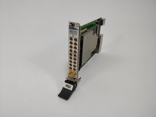
- I/O Connector: 7 SMA jacks (1 COM + 6 CHx)
- Operating Temperature: 0°C to 55°C (32°F to 131°F)

NI PXI-2597
The Real-World Problem It Solves
IEEE 488 limits you to 20 meters and 15 devices, which fails when you need instruments in an EMC chamber or on a factory floor. This extender pushes GPIB to 1 kilometer over fiber while providing electrical isolation between your controller and the remote bus.
Where you’ll typically find it:
- Aerospace and defense test systems routing multiple RF sources to analyzers
- Semiconductor ATE testing high-frequency signal paths
- Wireless communication test benches switching between antenna arrays
Bottom line: It routes six RF sources to one destination with built-in termination to prevent reflections that could fry your expensive microwave equipment.
Hardware Architecture & Under-the-Hood Logic
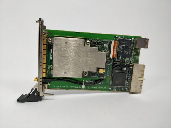
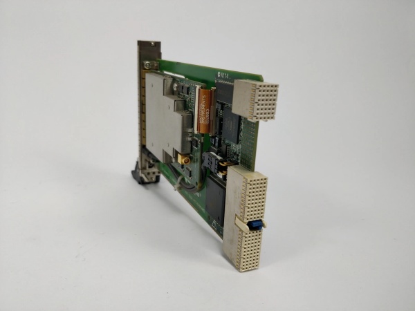
The PXI-2597 uses Radiall R574 electromechanical relays with non-latching contactors. Each of the six input channels connects to a common output through a single-pole six-throw (SP6T) configuration. Unselected channels terminate internally to 50 Ω to maintain impedance matching.
Signal flow and processing logic:
- Input Reception: RF signal enters through CH0-CH5 SMA connectors.
- Relay Selection: PXI backplane commands trigger the selected Radiall relay coil.
- Contact Closure: Selected relay connects input channel to COM port.
- Termination: Unselected channels shunt to internal 50 Ω termination.
- Output Delivery: Signal exits through COM SMA connector to downstream equipment.
- PXI Interface: NI-SWITCH driver manages relay state via PXI bus.
- Trigger I/O: PXI trigger lines 0-7 support hardware-triggered switching.
NI PXI-2597
Field Service Pitfalls: What Rookies Get Wrong
Overdriving the Termination
Engineers assume the 150 W carry power spec applies to the terminators. It doesn’t—terminators are only rated for 1 W per channel, 3 W total. High-power RF on unterminated channels fries the termination resistors.
- Field Rule: Never apply more than 1 W average power to any terminated channel. If you’re switching high-power RF, ensure the selected source is the only one transmitting, and verify all other sources are muted or disconnected.
Switching Active RF Signals
NI explicitly warns against switching live RF. During the 15 ms relay transition, the channel is momentarily unterminated, causing reflections that can damage sensitive microwave sources.
- Quick Fix: Always mute or turn off RF sources before switching channels. Use the PXI trigger lines to synchronize switching with source output control. If you must hot-switch, verify your source can handle open-circuit reflections.
Overtorquing SMA Connectors
Applying too much torque during installation or routine connection changes damages the SMA jack threads and the relay contacts behind them. This causes intermittent connections at high frequencies.
- Field Rule: Torque SMA connectors to 0.8-1.1 N·m (7-10 in·lbs) maximum. Use a torque screwdriver for critical connections. Never finger-tighten beyond resistance point, and never use pliers.
Ignoring Relay Life Tracking
The 2 million cycle life seems endless, but high-throughput ATE systems burn through relays fast. Engineers skip monitoring relay counts and face unexpected downtime when a relay fails mid-test.
- Field Rule: Enable relay count tracking in NI-SWITCH and log cycles per channel. Set predictive maintenance alerts at 1.5 million cycles. Replace relays before failure in production environments.


