
Description
Hard-Numbers: Technical Specifications
- Switching Configuration: 2-wire matrix (configurable as 4×32, 8×16, or dual 4×16)
- Crosspoints: 128 total (64 per bank, 2 banks onboard)
- Maximum Switching Voltage: 150 VDC / 150 VACrms (Channel-to-Channel and Channel-to-Ground)
- Maximum Switching Current: 1 A per channel
- Maximum Carry Current: 2 A per channel
- Maximum Module Current: 8 A total
- Maximum Switching Power: 30 W / 37.5 VA per channel
- Relay Type: Electromechanical, latching (field-replaceable)
- Contact Material: Silver palladium with gold plating
- DC Path Resistance: Initial <1 Ω, End-of-Life ≥2 Ω
- Thermal EMF: <9 μV (typical)
- Single Crosspoint Bandwidth: >10 MHz (50 Ω system)
- Crosstalk (50 Ω system): 10 kHz <–80 dB, 100 kHz <–65 dB, 1 MHz <–50 dB
- Relay Operate Time: 1 ms typical, 3.4 ms maximum (at 20°C)
- Maximum Scan Rate: 120 crosspoints/second
- Expected Relay Life (Electrical): 5×10⁷ cycles mechanical, 1×10⁵ cycles at 30 VDC/1 A resistive load
- Trigger Input: PXI trigger lines 0–7, minimum pulse width 150 ns
- Trigger Output: PXI trigger lines 0–7, programmable pulse width 1 μs to 62 μs
- Power Requirements: PXI: 6 W at 5 V / 2.5 W at 3.3 V | PXI Express: 7.5 W at 12 V / 2.5 W at 3.3 V
- Operating Temperature: 0°C to +55°C
- Storage Temperature: -20°C to +70°C
- Relative Humidity: 5% to 85%, non-condensing
- Maximum Altitude: 2,000 m (indoor use only)
- Dimensions: 3U, one-slot PXI/cPCI module: 21.6 × 2.0 × 13.0 cm (8.5 × 0.8 × 5.1 in.)
- Weight: 289–410 g (10.2–15 oz) depending on configuration
- Front Panel Connector: 100-pin HDI (High-Density Interconnect) or 200-pin LFH Matrix 50 receptacle (depending on terminal block)
- Safety Rating: Measurement Category I, 150 V maximum, withstands 800 V impulse voltage
- Compliance: IEC 61010-1, EN 61010-1, UL 61010-1, CSA 61010-1, RoHS compliant
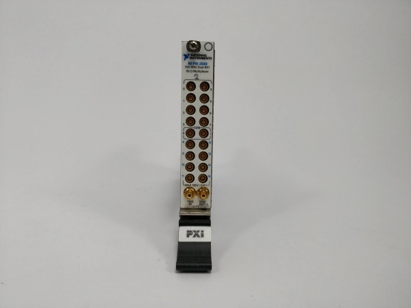
NI PXI-2529
The Real-World Problem It Solves
Automated test systems with hundreds of test points need flexible signal routing—instruments must connect to multiple DUTs or test nodes without rewiring. Traditional discrete wiring creates a cable nightmare, limits reconfigurability, and increases maintenance downtime when routing changes are required. The PXI-2529 gives you 128 configurable crosspoints in a single 3U slot, letting software define signal paths dynamically. Need to route DMM channel 1 to test point 45? One command. Switch to test point 92? Another command. No manual patching, no screw terminals to rewire, and no downtime for topology changes.
Where you’ll typically find it:
- Automotive ECU/ECM Functional Test: Routing ignition, sensor, and power signals to DMMs, oscilloscopes, and CAN bus analyzers in high-volume production lines
- Consumer Electronics Production Test: Switching between smartphones, tablets, or PCBAs for functional validation—connecting power supplies, load banks, and measurement instruments without operator intervention
- Power Supply/Audio Equipment Validation: Multi-output power supply testing where each output must be sequenced to load banks and measurement equipment for efficiency and ripple analysis
- Aerospace/Defense Avionics Test: High-reliability switching for avionics box testing where Measurement Category I requirements and low thermal EMF are mandatory for precision measurements
Bottom line: This module is your signal router in a box. When it fails, your test system’s flexibility dies—you’re locked into whatever configuration was last programmed, and you can’t route signals to different instruments or DUTs without physically rewiring or swapping the module.
Hardware Architecture & Under-the-Hood Logic
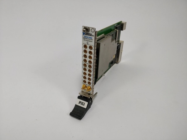
The PXI-2529 is a 3U PXI/PXIe card containing two independent banks of electromechanical latching relays arranged in a 2-wire matrix topology. Each bank has 4 rows and 16 columns, providing 64 crosspoints per bank (128 total). The module connects to the PXI backplane for power, communication (PXI trigger bus, PXI bus), and connects to external signals via front-mounting terminal blocks (TB-2634, TB-2635, or TB-2636). Latching relays maintain their state without continuous power draw—critical for test systems that must preserve configuration through power cycles.
- Host software sends command via PXI bus to NI-SWITCH driver (IVI-compliant API) specifying channel connection (e.g., “niSwitch_Connect(channel1=’r0′, channel2=’c15′)”)
- Driver translates to relay address and writes to module’s control registers over PXI backplane—determines which bank (0 or 1), row (R0–R3), and column (C0–C15) to activate
- Onboard FPGA/CPLD decodes command and drives relay coil control circuitry—applies pulse to latching relay coil (set or reset pulse, ~5–10 ms duration)
- Latching relay switches contacts—silver palladium contacts make connection between selected row and column, establishing signal path through 2-wire matrix (differential pair)
- Signal flows through relay contacts from DUT/instrument to measurement/instrument path—path resistance starts <1 Ω, increases as contacts age over relay lifetime
- Relay count tracking circuitry increments internal counter each time a relay is actuated—software can query this counter for predictive maintenance (relay life expectancy)
- Trigger input/output paths: If PXI trigger line receives pulse (min 150 ns width), module executes pre-loaded scan list without host processor intervention—enables deterministic switching synchronized with external instruments (e.g., DMM measurement complete trigger)
- Thermal EMF compensation: Relays designed with matched dissimilar metals and low thermal offset characteristics (<9 μV)—prevents thermocouple effect from corrupting low-voltage measurements (µV-level signals)
- Hardware protection: Overcurrent detection on relay driver coils, ESD protection on front panel connector pins, and safety interlock (terminal block removal disconnects matrix from backplane) prevent damage from wiring faults or accidental contact
NI PXI-2529
Field Service Pitfalls: What Rookies Get Wrong
Ignoring Relay Life Tracking Until Failure
Techs run test systems for months without checking the onboard relay cycle counter. The PXI-2529 tracks every relay actuation internally—software can query this count anytime. Rookies wait until a relay fails (open or stuck contact) before taking action, causing test failures, scrap units, or extended downtime troubleshooting which crosspoint died. Relays degrade gradually—contact resistance rises, thermal EMF drifts, switching time increases—before complete failure.
Field Rule: Query relay cycle counters monthly or after a defined number of test runs (e.g., every 10,000 DUTs). Compare to expected life ratings (1×10⁵ cycles at 30 VDC/1 A resistive). If any relay exceeds 80% of rated life, pre-emptively replace the module or plan relay-level refurbishment. NI relays are field-replaceable—soldered relays can be swapped by skilled techs, or return module to NI for refurbishment. Log counter trends to predict failures before they happen.
Mixing High and Low Voltage Signals Without Isolation
The module is rated Measurement Category I, 150 V maximum. Rookies route hazardous voltages (>42.4 Vpk/60 VDC) onto the same matrix as low-level measurement signals (µV range from thermocouples or strain gauges). While the module can handle 150 V, mixing voltage levels risks safety and accuracy—a wiring fault or contact bounce can inject hazardous voltage into measurement paths, damaging instruments or corrupting precision data. NI explicitly warns against this in datasheet.
Quick Fix: Segregate voltage levels across separate modules or matrix banks. If you must mix levels, ensure proper isolation between signal sources and use external protection circuits (TVS diodes, opto-isolators) on low-voltage paths. Never route mains voltage (115/230 VAC) through this module—it’s not designed for Category II/III/IV. Label terminal blocks clearly with voltage ranges to prevent future wiring errors.
Forgetting to Use Suppression Diodes on Inductive Loads
Switching motors, solenoids, or inductive transformers? Inductive kickback generates voltage transients exceeding the 150 V rating when relay contacts open. Rookies connect inductive loads directly to matrix without snubber circuits. Every switch cycle spikes contacts with hundreds of volts—arcing occurs, contacts pit and weld, relay life drops from 100,000 cycles to a few thousand. You’ll see erratic test results, intermittent opens, and early module failure.
Field Rule: Add flyback diodes (inverse-parallel across inductive load) or RC snubber networks directly at the load, not at the matrix terminals. For DC inductive loads, use diodes rated 2× load current with reverse voltage >2× supply. For AC inductive loads, use RC snubbers (100 Ω/0.1 μF typical). Measure transient voltage with an oscilloscope during first switch cycle—verify spikes stay under 150 V. NI provides detailed guidance on transient suppression (Info Code: induct).
Misconfiguring Terminal Block Topology for 8×16 vs 4×32 Matrix
The PXI-2529 supports multiple topologies via different terminal blocks (TB-2634, TB-2635, TB-2636). Rookies install TB-2634 (4×32 configuration) and then wire it expecting 8×16 behavior—or worse, remove jumper resistors to create dual 4×16 without understanding the pinout changes. The two onboard banks (4 rows × 16 columns each) can be combined for 4×32 (rows 0–7, columns 0–15), kept separate for dual 4×16, or combined with different wiring for 8×16. Wrong topology means your software rows/columns don’t match physical wiring—garbage data, no connectivity, or shorted signals.
Field Rule: Verify terminal block part number before installation matches your required topology. TB-2634 = 4×32 or dual 4×16 (ribbon cable headers, requires external sockets). TB-2635 = 8×16 (screw terminals, direct wiring). TB-2636 = 4×32 (screw terminals). Refer to NI’s topology diagrams—pinout changes dramatically between configurations. If using custom wiring without a terminal block, consult the 100-pin HDI front panel connector pinout (documented in NI manuals) and map rows/columns manually. Label terminal blocks with topology type after installation.
Neglecting to Account for Relay Settling Time in High-Speed Tests
Techs assume the 3.4 ms max operate time is the only delay. But certain applications—high-impedance measurement circuits, low-current signals, or sensitive instrumentation—require additional settling time after relay closure before measurements are valid. Rovers push scan rates to the 120 crosspoints/second limit without accounting for settling, resulting in measurement errors that drift from test to test. The DMM might read stable, but the measurement was taken before the relay contact bounce settled and thermal EMF stabilized.
Quick Fix: Determine required settling time empirically during system commissioning. Connect a known stable source to one matrix input and a high-impedance DMM to an output. Trigger a relay closure and log DMM readings vs. time—identify when values stabilize (typically 5–20 ms beyond relay operate time for precision measurements). Program software to add this delay between switch command and measurement. If maximum throughput is critical, use the hardware trigger feature—synchronize DMM measurement trigger with relay settling rather than relying on software timing loops.
Overloading the Module’s 8 A Total Current Limit
Each channel handles 2 A carry current, 1 A switching current—rookies do the math per channel and forget the module total limit: 8 A maximum across all relays simultaneously. If you wire 10 channels each carrying 1 A, you’re at 10 A total—module overheats, shuts down, or blows the PXI backplane fuse. Symptoms include intermittent resets, thermal shutdowns during high-current tests, or random relay failures from overstressed driver circuits.
Field Rule: Sum expected currents for all simultaneously closed relays in your test configuration. Keep total under 8 A. If your test requires more current, use multiple modules or external high-current switches (e.g., PXI-2567 for 50 V/600 mA per channel). Monitor module temperature during extended high-current runs—if chassis gets hot (>45°C ambient inside), add chassis cooling fans or derate current. PXI backplane provides 5 V/3.3 V power but has current limits per slot—don’t assume infinite current availability.
Commercial Availability & Pricing Note
Please note: The listed price is for reference only and is not binding. Final pricing and terms are subject to negotiation based on current market conditions and availability.


