
Description
Hard-Numbers: Technical Specifications
- Protocol Support: CAN 2.0A (11-bit ID) and CAN 2.0B (29-bit ID)
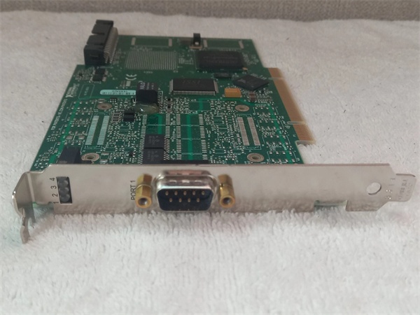
- Port Count: 2 independent CAN ports (9-pin D-Sub connectors)
- Baud Rate: Up to 1 Mbit/s per port
- Bus Interface: 32-bit PCI, 33 MHz, 5 V
- Isolation Rating: 1000 V RMS (channel-to-bus isolation)
- Operating Temperature: 0 to 55 °C (32 to 131 °F)
- Power Draw: 5 V at 0.8 A (typical), 5 V at 1.2 A (max)
- Termination: Software-configurable 120 Ω termination per port
- Input Impedance: 20 kΩ differential
- CAN Transceiver: ISO 11898-2 compliant

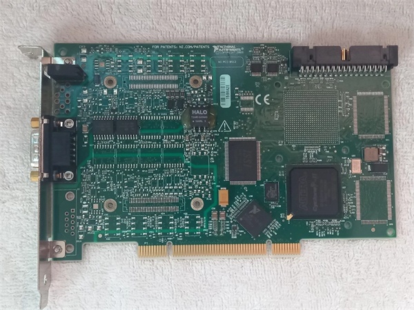
PCI-8512
The Real-World Problem It Solves
When you need to bridge a standard PC or industrial controller to a CAN network without getting burned by ground loops or noise, this card gets the job done. The isolation keeps your gear safe when you’re connecting to noisy vehicle harnesses or plant floor machinery.
Where you’ll typically find it:
- Automotive test benches running ECU diagnostics or calibration
- Industrial automation cells where PLCs or PCs monitor CAN-based sensor networks
- Aerospace ground support equipment interfacing with avionics busses
Bottom line: It provides a reliable, isolated bridge between PCI-based computing platforms and CAN networks in electrically harsh environments.
Hardware Architecture & Under-the-Hood Logic
The PCI-8512 sits on the PCI bus and communicates with host software through a memory-mapped interface. Each CAN port has its own dedicated controller and transceiver, with optical isolation separating the bus side from the host side.
Signal flow and processing logic:
- PCI Interface: Host CPU writes messages to card memory via PCI bus.
- Message Buffer: On-board FPGA manages transmit/receive queues and handles CAN 2.0A/B protocol.
- CAN Controller: Each port’s independent controller manages arbitration, error handling, and bit timing.
- Optical Isolation: Digital signals cross through optocouplers, breaking ground loops between PC and CAN bus.
- CAN Transceiver: Converts isolated logic levels to differential CAN_H/CAN_L voltages per ISO 11898-2.
- Physical Layer: 9-pin D-Sub connector delivers balanced differential signals to the bus.
PCI-8512
Field Service Pitfalls: What Rookies Get Wrong
Improper Termination
New engineers often forget termination on a short bus, thinking it’s “optional” or leaving the default setting wrong. This causes signal reflections that corrupt frames and trigger error counts.
- Field Rule: Always enable 120 Ω termination on both ends of the bus, and disable it on all intermediate nodes. Verify with a multimeter across CAN_H and CAN_L at the device—it should read 60 Ω on a properly terminated two-node bus.
Grounding the Shield Incorrectly
Shield ground gets tied to chassis ground at both ends, creating ground loops that bypass isolation and induce noise. This defeats the whole purpose of the isolation barrier.
- Quick Fix: Connect the cable shield to ground only at the CAN bus master end. Leave the shield floating at the PCI-8512 side unless you’re in a specific single-point-ground scenario.
Ignoring Error Frames
When the red FAULT LED flickers or the driver logs “Bus Off,” rookie engineers assume the card is dead and swap it immediately. Most of the time, it’s a cabling, termination, or baud rate mismatch issue.
- Field Rule: Check the error counters in NI MAX or your application software. If the bus goes passive or off, inspect your wiring first—check for shorts, open terminations, or baud rate mismatches before pulling hardware.


