
Description
Hard-Numbers: Technical Specifications
- Extension Distance: Up to 1 km (using T7 fiber-optic cable)
- Transfer Rate (IEEE 488.1) : Up to 1.1 MB/s
- Transfer Rate (HS488) : Up to 2.8 MB/s
- Device Loading: Up to 13 additional devices per extension (28 total including extenders)
- Fiber Connector: ST-style optical connector (62.5/125 µm core/clad)
- Operating Wavelength: 850 nm
- GPIB Interface: IEEE 488.1 and IEEE 488.2 compliant
- Operating Temperature: 0°C to 55°C (32°F to 131°F)
- Power Input: 100-240 V AC (regional variants) or 24 V DC
- Power Draw: Approximately 8 W typical
- Dimensions: 8.9 × 14.4 × 4.1 cm (3.5 × 5.65 × 1.62 in.)
- Weight: 0.25 kg (0.55 lb.)

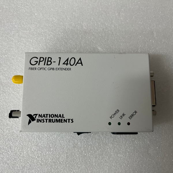
NI GPIB-140A
The Real-World Problem It Solves
IEEE 488 slams you with a 20-meter cable limit and 15-device cap, which is useless when you need to run instruments in an EMC chamber or control equipment on the factory floor from a remote office. This extender pushes GPIB to 1 kilometer over fiber while providing electrical isolation between your controller and the remote bus.
Where you’ll typically find it:
- EMC test chambers where instruments inside the shielded room connect to external controllers
- Automotive production lines with distributed test stations spanning large facilities
- Remote calibration labs where instruments are isolated from the control computer
Bottom line: It breaks the IEEE 488 physical barrier without changing your software, letting you put instruments where they belong instead of where the cable length dictates.
Hardware Architecture & Under-the-Hood Logic
The GPIB-140A sits between two GPIB buses, translating electrical GPIB signals into optical data for transmission over fiber. Each extender continuously monitors local GPIB activity and converts it to a serial protocol for transmission to the paired unit.
Signal flow and processing logic:
- GPIB Monitoring: Local GPIB interface detects handshake lines and data bus activity.
- Message Interpretation: On-board logic decodes IEEE 488.1/488.2 commands and data.
- E/O Conversion: Electrical signals drive an optical transmitter (HFBR1414 or equivalent).
- Fiber Transmission: Optical data travels over fiber (up to 1 km at 850 nm wavelength).
- O/E Conversion: Remote extender’s optical receiver (HFBR2416 or equivalent) converts light back to electrical signals.
- GPIB Reconstruction: Remote extender regenerates IEEE 488 signals on the second GPIB bus.
- Mode Handling: Buffered mode uses FIFO buffers for high-speed transfers; unbuffered mode maintains strict interlocked handshaking.
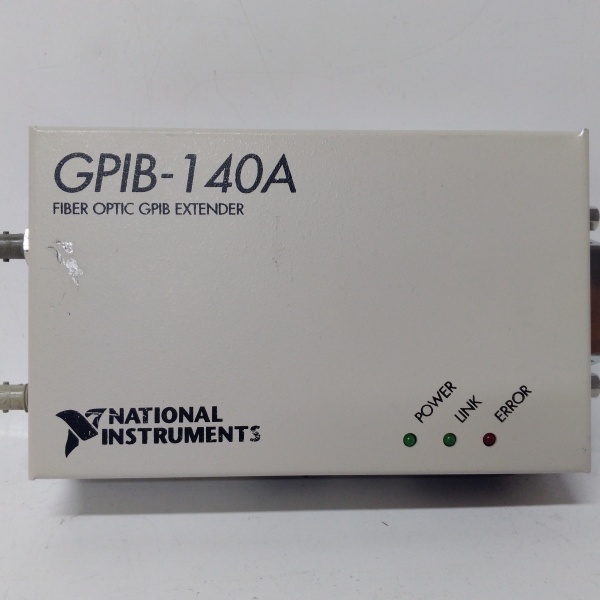
NI GPIB-140A
Field Service Pitfalls: What Rookies Get Wrong
Mismatched DIP Switch Configurations
Two extenders on the same link must have identical DIP switch settings for transfer mode (buffered/unbuffered) and HS488 enable. If they don’t match, the link won’t establish or you’ll get corrupted data.
- Field Rule: Verify both extenders have the same DIP switch positions before installing. Take a photo of each extender’s switches during commissioning and store it with your documentation.
Using Wrong Fiber Cable Type
The GPIB-140A requires T7 fiber rated for 850 nm wavelength and 1 km maximum distance. Plugging in a T8 cable (rated for 1300 nm) or standard telecom fiber causes signal loss or complete link failure.
- Quick Fix: Always use NI T7 fiber-optic cable (part numbers 182805-010 through 183164-01K). Label both ends of the fiber with the maximum length to prevent accidental swapping with longer T8 cables.
Forgetting Shielded GPIB Cables
Some techs run standard unshielded GPIB cables from the extender to instruments, assuming the fiber isolation solves all noise problems. This creates RF interference and violates FCC compliance.
- Field Rule: Use Type X1 or X2 double-shielded GPIB cables between the extender and instruments. Never use unshielded cables—this device requires shielded GPIB connections to meet emissions standards.


