
Description
Key Technical Specifications
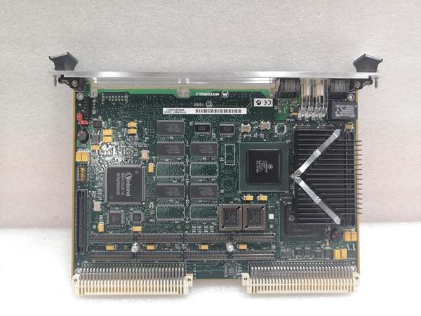
Model Number: MVME2400 (Series Baseline)
Manufacturer: Motorola (now NXP/Emerson/Abaco Systems through acquisitions)
Product Family: MVME2400 Series VMEbus Processors (PowerPlus II Architecture)
Form Factor: 6U VME (233.4 mm × 160 mm / 9.2″ × 6.3″)
Processor: Motorola PowerPC 750 (MPC750) 32-bit RISC microprocessor
Clock Speed: 300-450 MHz (varies by variant: MVME2431 @ 366 MHz, MVME2434 @ 350 MHz, MVME2400-0361 @ 450 MHz)
Cache: 32 KB L1 instruction cache, 32 KB L1 data cache; 1 MB backside L2 cache
Memory: 32 MB to 512 MB on-board ECC SDRAM (Error-Correcting Code)
Memory Bus: 100 MHz local bus with synchronous DRAM (SDRAM) technology
Storage: 8 MB on-board Flash memory; up to 1 MB firmware capacity; CompactFlash slot; EIDE interface
NVRAM: 8K x 8 with replaceable battery backup
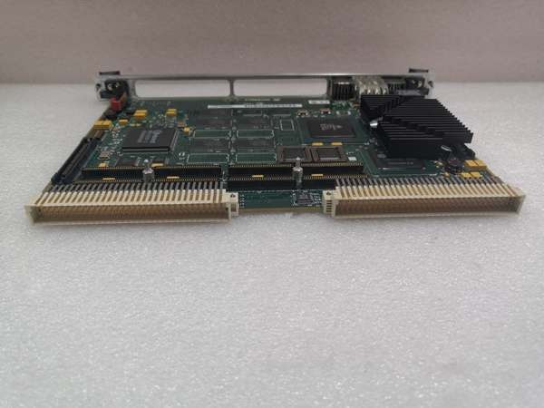
VMEbus Interface: VME64x with 5-row 160-pin DIN connector (100% backward compatible with VME64)
PCI Buses: 64-bit PCI bus; PowerPlus II architecture with processor/memory bus to PCI bridge
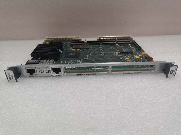
PMC Expansion: Two 32/64-bit PMC expansion slots (IEEE P1386.1 compliant) with front panel and P2 I/O
PCI Expansion: 64-bit PCI expansion mezzanine connector
Ethernet: 10/100 Mb/s Ethernet interface
Serial Ports: Two asynchronous serial ports (RS-232/422/485); one dedicated debug port
Parallel Interface: Centronics parallel port
USB: USB 2.0 ports (on some variants)
Timers: Four 32-bit timers, one 16-bit timer, watchdog timer
VME Interrupts: 4-level requester, 7-level interrupter, 7-level interrupt handler
Power Supply: 5V DC (standard VME), 24V/48V options on some variants
Operating Temperature: 0°C to +70°C (standard); -20°C to +70°C or -40°C to +85°C (industrial/military variants)
Storage Temperature: -40°C to +85°C
Vibration: 1G RMS, 20-2000 Hz random; 6G RMS, 20-2000 Hz random
Altitude: Up to 15,000m
Firmware: On-board debug monitor with self-test diagnostics
Operating System Support: VxWorks, Linux, Windows CE
Motorola MVME2400
Field Application & Problem Solved
In the field, the biggest challenge with 1990s-era VME systems was the transition from older 680×0 processors to modern PowerPC architecture while preserving the VME ecosystem investment. Customers had thousands of dollars invested in VME chassis, I/O cards, and backplanes, but needed more performance than 25 MHz 68040s could deliver. The MVME2400 series solved this by introducing PowerPlus II architecture —a bridge between legacy VME and modern PowerPC performance—allowing drop-in replacement of older MVME1600/1700 series boards while maintaining VMEbus compatibility and adding PCI-based PMC expansion.
You will typically find this series in industrial automation (CNC machine tools, robotics, process control), military and aerospace (radar signal processing, mission computers, telemetry), telecommunications (switching equipment, base station controllers), and data acquisition (high-speed recording, test systems). The MVME2400 was particularly popular from the late 1990s through early 2000s as a cost-effective upgrade path for aging VME installations. The dual PMC slots allowed customization for specific applications—add a graphics PMC for HMI, a communication PMC for fieldbus, or a custom I/O PMC without changing the base platform.
Its core value is performance upgrade with ecosystem preservation. The PowerPC 750 delivered 3-5x the performance of previous 68060-based boards while using less power . The VME64x interface provided backward compatibility with existing VME64 backplanes while adding extra I/O pins for future expansion. The ECC SDRAM detected and corrected memory errors, essential for 24/7 industrial operation. The 100 MHz local bus and 1 MB L2 cache eliminated the memory bottlenecks that plagued earlier designs. For military applications, the -40°C to +85°C variants survived harsh environments without heaters or cooling.
Installation & Maintenance Pitfalls (Expert Tips)
Variant Suffixes Determine Specific Configuration
The MVME2400 is a series baseline, not a specific orderable part. The actual boards are MVME2431, MVME2432, MVME2434, MVME2400-0331, MVME2400-0351, MVME2400-0361, etc. . Each suffix indicates different processor speed, memory size, and features. A common field mistake is ordering “MVME2400” and receiving a 32 MB variant when you needed 512 MB. Always verify the full part number including suffix. The MVME2431 is typically 366 MHz with 32 MB ; MVME2432 is 333-366 MHz with 64 MB ; MVME2434 is 350 MHz with 128-512 MB ; MVME2400-0361 is 450 MHz with 512 MB .
PowerPlus II Architecture Requires Updated Drivers
The PowerPlus II architecture uses a different PCI bridge and memory controller than older MVME1600/1700 series. A common pitfall is assuming VxWorks or Linux BSPs from older boards will work. They won’t—the PCI enumeration, interrupt routing, and DMA handling are different. Obtain the MVME2400-specific BSP from Emerson/Abaco. If migrating from 680×0-based VME boards, you must recompile all software for PowerPC. The byte ordering (big-endian) is the same, but the instruction set and timing are completely different.
VME64x P2 Pinout Differs from VME64
The VME64x connector adds rows Z and D to the standard P1/P2 . While 100% backward compatible , the extra rows provide additional I/O. A common mistake is using legacy VME64 I/O cards in P2 and wondering why the extra pins don’t work. Verify your I/O cards are VME64x-compliant if you need the extra I/O. The PMC P2 I/O routing also differs from older designs—check your PMC card manual for VME64x compatibility.
PMC Card VME P2 I/O Compatibility
The dual PMC slots support both front-panel and P2 I/O . A frequent issue is installing a PMC card that expects P2 I/O routing, but the MVME2400’s P2 pinout doesn’t match. The IEEE P1386.1 standard defines PMC, but VME P2 implementation varies by vendor. Check the “PMC committee recommendations for PCI I/O when using the VME64 expansion connector” . If your PMC card works in a cPCI carrier but not in the MVME2400, the P2 routing is likely the issue.
Memory Size vs. Performance Trade-off
The MVME2400 supports 32-512 MB ECC SDRAM , but larger memory configurations can slow down bus cycles due to refresh overhead. A common mistake is specifying 512 MB “for future expansion” when 64 MB would suffice, then experiencing slightly slower memory access. For real-time applications, use the minimum memory that fits your application. The ECC overhead is minimal, but larger memory arrays have longer access latencies.
Flash Memory Programming Voltage
The 8 MB on-board Flash requires proper voltage levels during programming. A field pitfall is attempting to update Flash firmware with a marginal power supply or through a VME backplane with voltage drop. Flash corruption bricks the board. Always use a stable 5V supply with at least 10% margin during Flash updates. Use the on-board debug monitor for recovery if Flash becomes corrupted—it’s stored in a separate boot block.
NVRAM Battery Replacement
The 8K x 8 NVRAM with battery backup stores critical configuration. The battery is replaceable, but a common mistake is waiting for failure before replacement. At 5 years, battery voltage drops below reliable retention levels. Replace proactively during scheduled maintenance. Document your NVRAM settings (boot parameters, network addresses) so you can restore them after battery replacement. The “replaceable backup battery” is typically a coin cell—verify the part number (usually CR2032 or similar) before ordering spares.
Thermal Management in Sealed Enclosures
The MVME2400 dissipates more heat than older 680×0 boards due to the PowerPC 750 and 100 MHz bus. A common field issue is installing in a sealed NEMA enclosure with insufficient airflow. The processor overheats, causing intermittent failures or thermal shutdown. Verify your enclosure has forced air cooling with at least 200 LFM across the board. If using conduction cooling (military variants), ensure the thermal interface to the card guide is clean and properly torqued.
Motorola MVME2400
Technical Deep Dive & Overview
The Motorola MVME2400 is a VMEbus Single Board Computer series representing Motorola’s PowerPlus II architecture —a strategic bridge between legacy 680×0-based VME systems and modern PowerPC-based embedded computing. It was designed to preserve customer investment in VME infrastructure while delivering 3-5x performance improvement.
The architecture centers on the PowerPC 750 (MPC750) microprocessor , a 32-bit RISC design with superscalar execution and integrated memory management. The 32 KB/32 KB L1 cache and 1 MB backside L2 cache minimize memory latency, while the 100 MHz local bus with SDRAM provides high-bandwidth memory access. The ECC (Error-Correcting Code) detects and corrects single-bit memory errors, essential for industrial reliability.
The PowerPlus II architecture integrates the processor, memory controller, PCI bridge, and VME interface into a cohesive design optimized for embedded performance. Unlike earlier designs that used discrete chips for each function, PowerPlus II reduces board complexity and improves reliability while enabling the 64-bit PCI bus for high-speed I/O.
The VME64x interface uses a 5-row 160-pin DIN connector that adds rows Z and D to the standard VME P1/P2. This provides extra I/O pins while maintaining 100% backward compatibility with existing VME64 backplanes and cards. The VME bridge supports A16/A24/A32 addressing, D8/D16/D32 data transfers, and full VME interrupt handling .
The dual PMC (PCI Mezzanine Card) slots are a key feature, providing IEEE P1386.1-compliant expansion for application-specific I/O. These slots support both front-panel and P2 I/O, allowing flexible system configuration. The 64-bit PCI expansion mezzanine enables additional PCI devices beyond the two PMC slots.
Peripheral integration includes 10/100 Ethernet for network connectivity, dual serial ports for console and device communication, parallel port for legacy peripherals, and multiple timers plus watchdog for real-time control. The on-board debug monitor provides low-level diagnostics and boot support without external tools.
From a system architecture perspective, the MVME2400 functions as a general-purpose embedded processor on the VME bus. It can operate as VME bus master, slave, or system controller, supporting multiprocessor configurations. The deterministic VME bus timing, combined with PowerPC performance and PCI expansion, makes this suitable for real-time control, data acquisition, and signal processing applications.
The series’ modular design philosophy—base platform with PMC customization—allowed Motorola to address diverse markets with minimal hardware variants. Customers could specify processor speed, memory size, and I/O configuration by selecting the appropriate suffix variant, while the underlying PowerPlus II architecture provided consistent software and mechanical interfaces.


