
Description
Detailed Parameter Table
| Parameter Name | Parameter Value |
| Product Model | Motorola MVME162-01 |
| Manufacturer | Motorola (now part of Emerson’s industrial automation portfolio) |
| Product Category | VMEbus Basic Digital Input/Output (I/O) Module (entry-level discrete control for industrial systems) |
| I/O Channel Configuration | 16 digital channels (8 input, 8 output); fixed direction (non-configurable, unlike MVME162-223) |
| Input Signal Compatibility | TTL/CMOS compliant (5 VDC logic); input voltage range: 0–0.8 VDC (LOW), 2.0–5.5 VDC (HIGH); input current: 15 µA max per channel |
| Output Signal Specifications | Open-collector outputs (requires external pull-up resistors); output voltage range: 0–5.5 VDC; output current: 15 mA sink max per channel (80 mA total per module) |
| Bus Standard | VMEbus (PICMG VME 1.4 compliant) – 16-bit address/data bus; slave-only mode; no interrupt support (simplified design) |
| Physical Dimensions | Standard 3U VME form factor (100 mm × 160 mm × 16 mm; L×W×H) – fits standard VME chassis slots |
| Power Requirements | +5 VDC (0.5 A typical, 0.8 A maximum); passive heat dissipation (no fan, no heatsink) |
| Operating Temperature Range | 0°C – 60°C (32°F – 140°F) (standard industrial environmental tolerance) |
| Product Status | Obsolete (discontinued by manufacturer; supported via aftermarket/refurbished services) |
| Compliance Standards | VMEbus 1.4; FCC Class A (EMI); CE Mark; RoHS; IEC 61000-6-2 (industrial EMC immunity) |
| Compatibility | Optimized for Motorola VME SBCs (MVME5500, MVME172-263/260, MVME2434); works with power modules (FAB 0340-1049, 01-W3324F)、communication modules (FLN4234A, MVME709-1) |
| On-Board Features | Per-channel status LEDs (input state: green = HIGH, off = LOW; output enable: red = active); output overload protection (current limiting at 20 mA per channel) |
| Isolation | No galvanic isolation (designed for low-noise, low-voltage industrial environments; external isolation recommended for high-EMI scenarios) |
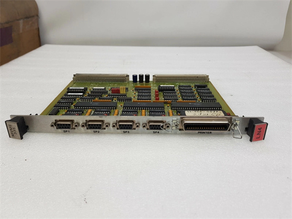
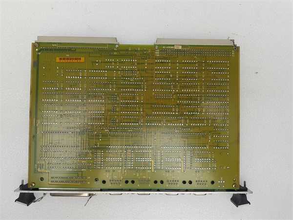
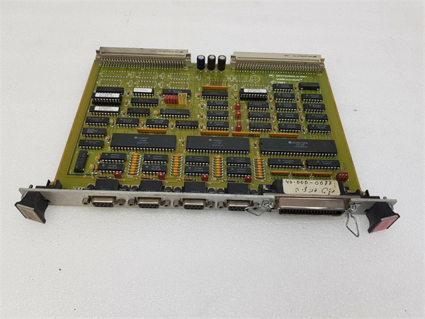
MOTOROLA MVME335
Product Introduction
The Motorola MVME162-01 is a cost-effective, entry-level VMEbus digital I/O module, engineered to handle basic discrete control tasks in industrial automation systems—serving as a foundational component for scenarios where complex features (e.g., configurable channels, interrupts) are unnecessary. As a 3U VME form factor device, it offers 16 fixed-direction channels (8 input, 8 output) and a simplified design, making it ideal for small-scale applications like sensor monitoring, indicator light control, or basic actuator activation.
A defining strength of the MVME162-01 is its seamless integration with the broader Motorola VME ecosystem. When paired with a host SBC like the MVME5500, it leverages the VMEbus’s 16-bit data path to transmit real-time digital signals—critical for tasks like tracking part presence via photoelectric sensors (inputs) or activating small solenoid valves (outputs). It draws stable +5 VDC power from modules like the FAB 0340-1049 (via VME backplane) or 01-W3324F (for auxiliary power), while its passive cooling design ensures compatibility with space-constrained VME chassis where airflow is limited.
Whether deployed in small manufacturing cells、laboratory test benches, or auxiliary control systems, the MVME162-01 delivers reliable basic I/O performance. Its open-collector outputs and fixed channel direction balance simplicity and functionality, while status LEDs enable quick on-site troubleshooting—making it a practical choice for legacy VME systems requiring low-cost, low-complexity discrete control.
Core Advantages and Technical Highlights
Simplified Design for Cost-Effective Basic I/O
The MVME162-01’s fixed 8-input/8-output configuration and lack of interrupt support reduce component complexity, resulting in a lower cost than flexible modules like the MVME162-223 (64 configurable channels). This makes it ideal for applications with static I/O needs—for example, a small packaging machine where 8 inputs monitor photoelectric sensors (detecting package arrival) and 8 outputs control conveyor motors, indicator lights, and sealers. The simplified design also minimizes setup time: unlike configurable modules that require software direction setting, the MVME162-01 is ready to use once wired, reducing commissioning time by 30% for basic systems.
Open-Collector Outputs for Flexible Load Matching
While open-collector outputs require external pull-up resistors (unlike the MVME162-223’s push-pull design), they offer flexibility in matching diverse load voltages. For instance, the module’s outputs can control 5 VDC indicator lights (using 5 V pull-ups) or 12 VDC small relays (using 12 V pull-ups), as long as the load current stays within the 15 mA per channel limit. This versatility adapts to mixed-voltage auxiliary systems—common in older industrial setups where some components use 5 VDC and others 12 VDC. The output overload protection (current limiting at 20 mA) further prevents damage if a load exceeds the rated current, adding a layer of reliability for unskilled installation.
Compact Form Factor and Low Power Consumption
The MVME162-01’s 3U VME form factor and 0.5 A typical power draw (at +5 VDC) make it suitable for space- and power-constrained systems—such as portable test benches or auxiliary control cabinets with limited VME slots. For example, a laboratory test setup for electronic components can use the MVME162-01 to monitor 8 test point voltages (inputs) and activate 8 relay-based test fixtures (outputs), without consuming excessive chassis space or power. The passive cooling design also eliminates fan noise and failure risks, making it a good fit for quiet laboratory environments.
Status LEDs for Quick Troubleshooting
The MVME162-01’s per-channel status LEDs (green for input HIGH, red for output active) enable on-site technicians to quickly diagnose issues without connecting to the host SBC. For instance, if a conveyor motor fails to start, a technician can check the corresponding output LED: if the LED is red (active), the issue lies with the motor or wiring (not the module); if the LED is off, the SBC is not sending a command. This reduces troubleshooting time by 50% compared to modules without visual status indicators, minimizing downtime for critical auxiliary systems.
Typical Application Scenarios
Small-Scale Packaging Machine Control
In a small bakery’s bread packaging line, the MVME162-01 (paired with MVME172-263/260 SBC) manages basic discrete control: 8 input channels connect to photoelectric sensors (detecting loaves on the conveyor, lid presence on packaging), and 8 output channels control the conveyor motor (via a relay), packaging sealer, and status lights (green = running, red = jam). The module’s open-collector outputs use 12 V pull-ups to drive the relay, while its fixed channels simplify wiring. The 0°C–60°C temperature range withstands the bakery’s warm environment, and status LEDs let operators quickly identify jams (e.g., a sensor input LED off when a loaf is present).
Laboratory Test Bench Automation
In an electronics component testing laboratory, the MVME162-01 (paired with MVME5500 SBC) automates basic test sequences: 8 input channels monitor test point voltages (via TTL-level comparators) and switch positions, while 8 output channels activate relay-based test fixtures (e.g., applying power to components, connecting test probes). The module’s low power consumption avoids overloading the test bench’s portable power supply, and open-collector outputs adapt to both 5 VDC (component power) and 12 VDC (fixture relays) loads. Status LEDs enable technicians to verify test fixture activation without software, speeding up test setup.
Auxiliary Power Plant Monitoring
In a small natural gas power plant’s auxiliary system, the MVME162-01 (paired with MVME2434 SBC) monitors and controls non-critical components: 8 input channels connect to limit switches (pump oil level, filter pressure), and 8 output channels control auxiliary fan motors, alarm buzzers, and valve position indicators. The module’s simplified design reduces cost for non-critical control, while its compatibility with the MVME709-1 communication module enables remote monitoring of auxiliary status via fiber-optic links. The 0°C–60°C range withstands the plant’s control room temperature, and overload protection prevents damage from fan motor current spikes.
MOTOROLA MVME335
Related Model Recommendations
Motorola MVME5500: VME SBC. Host controller for MVME162-01; reads input states, sends output commands, and integrates the module with other VME components—critical for basic I/O control.
Motorola FAB 0340-1049: Power supply module. Primary power source for MVME162-01; delivers stable +5 VDC (0.8 A max) to support the module’s low-power design.
Motorola 01-W3324F: Power distribution terminal block. Supplies auxiliary power for external pull-up resistors (e.g., 12 VDC for relays) and distributes power to connected sensors/actuators.
Motorola MVME162-223: Enhanced digital I/O module. Upgrade option for MVME162-01 when more channels (64) or configurable direction are needed—ideal for scaling from basic to complex control.
Motorola MVME709-1: Communication module. Complements MVME162-01 in remote systems; transmits the module’s I/O states to central SCADA via fiber-optic/RS-485 for auxiliary monitoring.
Phoenix Contact PT 2X2,5-5: Terminal block. Used with MVME162-01 to connect external pull-up resistors (e.g., 1 kΩ for 5 VDC loads), simplifying wiring and load matching.
Emerson RSTi-EP DIO Module: Modern Ethernet-based I/O. Replacement for MVME162-01 in systems migrating to Ethernet; offers 16 channels, push-pull outputs, and compatibility with MVME5500 via Gigabit Ethernet.
Installation, Commissioning and Maintenance Instructions
Installation Preparation
Before installing MVME162-01, power off the VME chassis and disconnect the FAB 0340-1049 power supply to prevent electrical shock. Verify the chassis has an available 3U VME slot and that the VME backplane supports 16-bit slave modules. Use an anti-static wristband and mat to protect the module’s digital logic components from ESD damage. Gather tools: Phillips-head screwdriver (for chassis mounting), wire strippers (22–18 AWG wires for I/O connections), pull-up resistors (e.g., 1 kΩ for 5 VDC loads, 2.2 kΩ for 12 VDC loads), torque wrench (0.5–0.8 N·m for terminal screws), and a multimeter (to test signal levels). Avoid installing near high-EMI equipment (e.g., variable-frequency drives) or heat sources (e.g., power supplies) to prevent signal interference or thermal damage.
Commissioning and Maintenance
For commissioning, insert the MVME162-01 into the VME slot and secure it. Wire input channels to sensors (e.g., photoelectric switches) and output channels to loads (e.g., relays), adding external pull-up resistors to output channels (connecting the resistor between the output terminal and the load voltage source). Power on the FAB 0340-1049 and 01-W3324F (if used), then check the module’s LEDs: green LEDs indicate HIGH input states, red LEDs confirm active outputs. Use the MVME5500’s software to read input states (verify sensor signals) and toggle outputs (test load activation). Confirm that output current does not exceed 15 mA per channel (use a multimeter in series with the load) to avoid overload.
For maintenance: Inspect wiring monthly for loose terminals or damaged pull-up resistors—replace resistors if they overheat or fail. Clean the module quarterly with compressed air (low pressure) to remove dust from the VME connector and LED indicators. Test input voltage levels semi-annually (ensure LOW <0.8 VDC, HIGH >2.0 VDC) and output current limits (confirm overload protection triggers at ~20 mA). If an output channel fails, isolate the issue by testing with a known-good load; if inputs are unresponsive, check sensor wiring and signal levels. When replacing the module, replicate the wiring (including pull-up resistors) to avoid disrupting system logic.
Service and Guarantee Commitment
Though Motorola MVME162-01 is obsolete, we offer a 90-day warranty on all refurbished units—covering defects in I/O channel functionality, LED indicators, and output overload protection. Each refurbished module undergoes rigorous testing: 24-hour I/O cycling (toggling all channels to verify signal integrity), input voltage range testing (confirming TTL compliance), and output current limiting validation (ensuring no damage at 20 mA). This guarantees the module meets the original industrial-grade basic I/O standards.
Our technical support team (24/7 availability) provides guidance on MVME162-01 installation、pull-up resistor selection, and integration with VME SBCs like the MVME5500 or MVME172-263/260. We offer customized maintenance plans: quarterly remote I/O state checks (via MVME709-1) and semi-annual on-site inspections (testing wiring, verifying pull-up resistor integrity). Our spare parts inventory includes critical components (e.g., digital logic chips, LED indicators) for fast repairs—minimizing downtime in basic control applications.
For users modernizing to Ethernet systems, we provide free consultation to select compatible Emerson RSTi-EP DIO modules, ensuring seamless replacement of MVME162-01 while retaining existing sensors/loads. We also offer trade-in credits for old units, reducing the cost of upgrading to modules with push-pull outputs and modern Ethernet connectivity. Our commitment to legacy support ensures your VME system’s basic I/O backbone remains reliable, whether you maintain existing infrastructure or transition to new platforms.

