
Description
Detailed Parameter Table
| Parameter Name | Parameter Value |
| Product Model | MOTOROLA MVME-147A |
| Manufacturer | Motorola |
| Product Category | 2-Slot Single Board Computer for industrial and embedded applications |
| Processor | MC 68030 enhanced 32-bit microprocessor (with options for different clock speeds like 16 MHz, 25 MHz, 33.33 MHz in the MVME 147 series; specific speed for MVME-147A may vary) |
| Clock Speed | Varies (options typically include speeds in the range relevant to the MVME 147 series as mentioned) |
| Memory | 4, 8 or 16 MB of shared DRAM; 512 KB SRAM with battery backup; 1MB flash memory for on – board monitor / debugger or user installed firmware |
| Storage | 8 k x 8 NVRAM and time – of – day clock with battery backup; additional storage options may be available through expansion |
| Expansion Interfaces | Four 16 – or 32-bit Industry Pack® ports with one DMA channel per port; two serial communication ports (console port as EIA – 232 – D DTE and second port user configurable for EIA – 232 – D / EIA – 422 (V. 36) DTE / DCE) |
| Bus Standard | 32 / D 64 VMEbus master / slave interface with system controller function; high – performance DMA support for VMEbus D64 and local bus memory burst cycles |
| Physical Dimensions | Dimensions: 263 × 138 × 88 mm (L×W×H) |
| Power Requirements | Dependent on system configuration; typically designed to operate with standard industrial power sources |
| Operating Temperature Range | Designed to operate within a range suitable for industrial environments (exact range may require further reference to product documentation) |
| Product Status | Varies; may be available new or as refurbished in the market; may be in different stages of lifecycle depending on availability |
| Compliance Standards | Complies with relevant industry standards for industrial computing (specific standards may require further research) |
| Compatibility | Compatible with VMEbus backplanes; designed to work with a variety of industrial and embedded system components |
| On-Board Features | On – board debugger and diagnostic firmware; four 28 / 32 – pin ROM / PROM / EPROM / EEPROM sockets; 4 k x 8 SRAM and time – of – day clock with battery; four EIA – 232 – D serial communications ports |
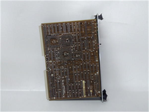
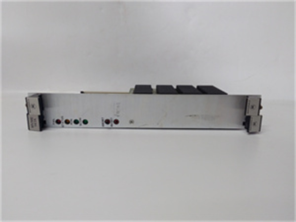
MOTOROLA MVME-147A
Product Introduction
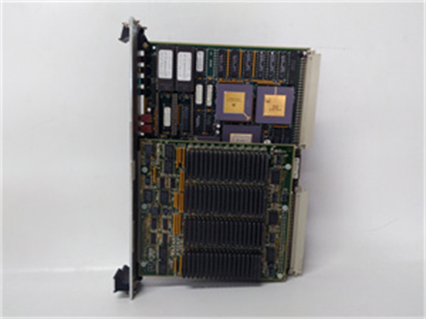
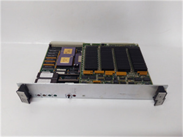
The MOTOROLA MVME-147A is a 2 – slot single board computer that has been a staple in industrial and embedded applications. Part of the MVME 147 series, it is engineered to offer reliable computing power in a compact form factor. With its enhanced 32 – bit MC 68030 microprocessor, it provides the necessary processing muscle for a wide range of tasks, from industrial control systems to data acquisition in embedded setups.
The MVME – 147A comes equipped with a diverse set of on – board resources and peripheral controllers. This not only eliminates the need for additional modules in the VMEbus backplane but also reduces costs and frees up valuable bus slots for other functions. Whether it’s used in a factory floor for controlling manufacturing processes or in a remote data collection station, the MVME – 147A has the potential to meet the demands of the application.
Core Advantages and Technical Highlights
High – Performance Processor for Efficient Computing
The MC 68030 enhanced 32 – bit microprocessor in the MVME – 147A is a significant advantage. It was one of the first general – purpose microprocessors with on – chip cache memory for both instructions and data. This cache memory increases the processor’s efficiency by 20 to 40 percent. The presence of a complete memory management unit (MMU) provides software protection and virtual memory functions, which are crucial for many applications. For example, in a complex industrial control system where multiple processes need to run simultaneously, the MMU ensures that each process has its own protected memory space, preventing data corruption and system crashes.
Abundant Memory Options for Data Handling
With options for 4, 8, or 16 MB of shared DRAM, along with 512 KB SRAM with battery backup and 1MB flash memory, the MVME – 147A can handle a substantial amount of data. The shared DRAM allows for quick access to data during real – time operations, while the battery – backed SRAM ensures that critical data is retained even during power outages. The flash memory can be used for storing on – board monitor/debugger software or user – installed firmware. In a data – logging application, the large DRAM can store incoming sensor data in real – time, and the flash memory can hold the logging software and configuration data.
Multiple Expansion Interfaces for Versatility
The four 16 – or 32 – bit Industry Pack® ports, each with one DMA channel, offer great expansion capabilities. These ports can be used to connect various modules such as additional communication interfaces, input/output modules, or specialized data acquisition modules. The two serial communication ports, with one configurable for different standards (EIA – 232 – D / EIA – 422 (V. 36) DTE / DCE), provide flexibility in communicating with other devices. In a network of industrial sensors, the serial ports can be used to connect to individual sensors, and the Industry Pack® ports can be used to expand the system with additional processing or communication modules.
Typical Application Scenarios
Industrial Control Systems
In an industrial control system, the MVME – 147A can be at the heart of the operation. It can control various manufacturing processes, such as regulating the speed of conveyor belts, controlling the flow of materials in a chemical plant, or monitoring the quality of products on an assembly line. The high – performance processor can execute complex control algorithms in real – time, while the multiple expansion interfaces can be used to connect to sensors, actuators, and other control devices. For example, the serial ports can be used to communicate with temperature sensors, and the Industry Pack® ports can be used to connect to motor control modules.
Data Acquisition in Embedded Systems
For embedded systems involved in data acquisition, the MVME – 147A is well – suited. It can collect data from a variety of sources, such as environmental sensors, vibration sensors in machinery, or power sensors in electrical systems. The large memory capacity allows it to store the acquired data for further processing or transmission. In a smart building monitoring system, the MVME – 147A can collect data from multiple sensors (temperature, humidity, occupancy) and use the on – board processing power to analyze the data and trigger appropriate actions, such as adjusting the HVAC system.
Related Model Recommendations
MVME – 147 Series Variants: Other models in the MVME 147 series may offer different processor speeds or additional features. For example, some variants may have higher clock speeds for more demanding applications, or different memory configurations to better suit specific data – handling requirements.
Industry Pack® Modules: A wide range of Industry Pack® modules can be paired with the MVME – 147A. These include communication modules (such as Ethernet or CAN bus modules), input/output modules for expanding digital or analog I/O capabilities, and data acquisition modules for specific sensor interfaces.
Power Supplies: Suitable industrial – grade power supplies should be selected based on the power requirements of the MVME – 147A and the associated peripheral devices. These power supplies should be able to provide stable power in industrial environments.
MOTOROLA MVME-147A
Installation, Commissioning and Maintenance Instructions
Installation Preparation
Before installation, ensure that the VMEbus backplane is properly configured and powered off. Verify that the target environment has sufficient space to accommodate the MVME – 147A’s dimensions (263 × 138 × 88 mm). Use anti – static equipment, such as an anti – static wristband and mat, to protect the board from electrostatic discharge during handling. Gather the necessary tools, including a screwdriver for mounting the board in the VMEbus slots and any cable – connecting tools required for attaching peripheral devices.
Commissioning and Maintenance
For commissioning, carefully insert the MVME – 147A into the appropriate VMEbus slots. Connect all the necessary power cables and peripheral cables, such as those for serial communication and Industry Pack® modules. Power on the system and check the on – board diagnostic LEDs (if available) to ensure proper startup. Use the on – board debugger and diagnostic firmware to perform initial tests, such as checking the processor functionality, memory integrity, and communication port operations.
For maintenance, regularly check the connections of all cables to ensure they are secure. Monitor the system’s performance, looking for any signs of abnormal behavior, such as slow data processing or communication errors. Periodically clean the board to remove dust, which can affect its performance, especially in industrial environments with high levels of particulate matter. If any components fail, such as a serial communication port or a memory module, follow the manufacturer’s guidelines for replacement.
Service and Guarantee Commitment
The availability of service and guarantee for the MVME – 147A may vary depending on the source of purchase. Some suppliers may offer a standard one – year warranty, covering defects in materials and workmanship. This warranty typically includes replacement or repair of the board if it fails under normal use. Technical support may be available from the manufacturer or authorized resellers. They can provide assistance with installation, configuration, and troubleshooting. In some cases, refurbished MVME – 147A boards may also be available, often with a shorter but still reasonable warranty period, along with pre – testing to ensure proper functionality.


