
Description
Key Technical Specifications
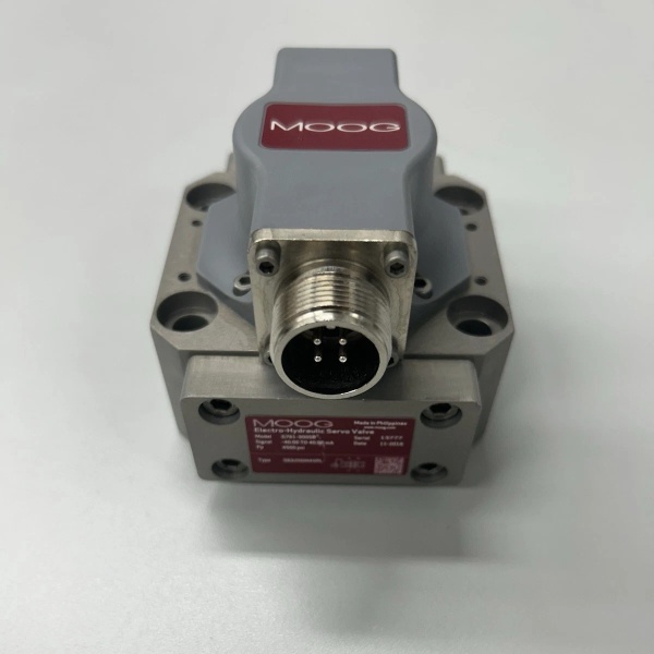
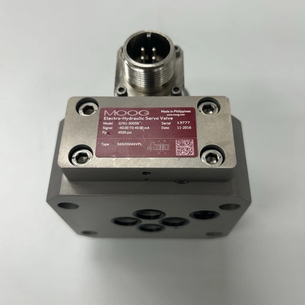
- Model Number: G761-3005
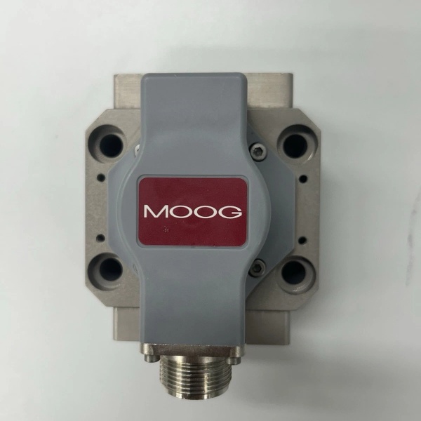
- Manufacturer: Moog Inc. (Industrial Motion Control Group)
- Valve Type: Two-stage mechanical feedback (MFB) servo valve (pilot-operated)
- Actuation Principle: Nozzle-flapper pilot stage + permanent magnet torque motor; sliding spool power stage with mechanical feedback wire
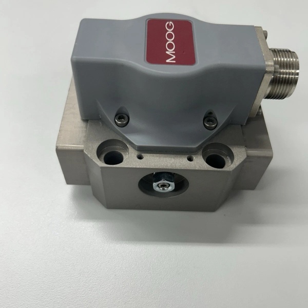
- Size Classification: ISO 10372 Size 03 (NG6) – 4-bolt flange (M6 x 1.0)
- Flow Capacity: 28 L/min (7.4 gpm) at Δp=35 bar (500 psi); 56 L/min (14.8 gpm) total flow at Δp=70 bar
- Maximum Operating Pressure: 315 bar (4570 psi) – continuous service; 350 bar (5075 psi) proof pressure
- Electrical Interface: Control Input: ±10V DC analog or ±40mA DC (single coil); Pilot Supply: 10-15 bar (145-217 psi) clean pressure; Connector: 6-pin DIN 43650 A (IP65 with sealed boot); Torque Motor Current: 40mA nominal, 80mA peak
- Response Time: 7ms (90% step response from 0–100% command)
- Operating Temperature: -20°C to +70°C (-4°F to +158°F)
- Fluid Requirements: Mineral oil (ISO VG 32–68), NAS 1638 Class 5 (pilot supply: NAS 1638 Class 5), max 85°C fluid temp
- Mounting Torque: 10 Nm (7.4 ft-lbs) – flange bolts
- Weight: 2.2kg (4.8 lbs)
- Seal Type: FKM (Viton) standard; NBR (Buna-N) optional
- Certifications: CE, RoHS compliant; ATEX/IECEx optional (Zone 2 hazardous areas – G761K variant)

MOOG G761-3005
Field Application & Problem Solved
In industrial hydraulic systems that prioritize reliability over complex electronics—think power plant auxiliary actuators, steel mill auxiliary roll stands, or medium-duty test rigs—the biggest headache is electronic feedback (EFB) valve failures. EFB valves with LVDTs are prone to damage from vibration, dust, or moisture in harsh environments. A Texas power plant wasted $90k/year replacing EFB valves on boiler feedwater actuators, where vibration shorted LVDT wiring. A Pennsylvania steel mill dealt with 3-hour downtime events when EFB valves failed on auxiliary roll positioners, halting coil processing.
This valve fixes that with its mechanical feedback (MFB) design—no fragile LVDTs or electronic feedback circuits. You’ll find it in: power plant auxiliary systems (boiler feedwater valves, damper control), steel mill auxiliary stands (edge guide actuators, tension control), medium-duty test rigs (static load simulation), and plastic extrusion machines (screw speed control). Its core value is rugged simplicity + cost-effectiveness—mechanical feedback resists vibration/dust/moisture, no pilot system complexity, and 50% lower replacement costs than EFB valves. For the Texas power plant, it cut valve replacement costs by 60% and eliminated LVDT-related downtime. For the steel mill, it reduced auxiliary system downtime by 85%.
Installation & Maintenance Pitfalls (Expert Tips)
- Mechanical Feedback Wire Alignment: Critical for Zero Deadband: Rookies bend or over-tension the feedback wire during installation, causing 1–2% deadband. I replaced a valve at an Ohio power plant where the tech kinked the wire—boiler feedwater flow fluctuated by 5%. Fix: Use Moog’s alignment tool (P/N B67728-003) to ensure the wire is straight, perpendicular to the spool axis, with no preload. Check alignment after mounting and before pressurizing.
- Fluid Cleanliness: NAS 1638 Class 5 Non-Negotiable: The nozzle-flapper pilot’s 0.3mm orifices clog with NAS 6 oil. A Michigan test rig’s valve stuck after 6 months because the client used 10µm filters—costing 2 days of testing. Fix: Install 5µm absolute filters (β10 ≥ 100 per ISO 16889) and test oil cleanliness every 1500 hours. De-aerate oil to prevent cavitation in the pilot.
- Pilot Pressure: Lock to 10–15 Bar: Too low (≤8 bar) slows response; too high (≥18 bar) wears the torque motor and feedback wire. A Tennessee extrusion plant’s screw speed was erratic until we adjusted the pilot regulator to 12 bar. Fix: Install a dedicated gauge on the pilot supply and check weekly—fluctuations mean a clogged filter or faulty regulator.
- Mounting Torque: 10 Nm Exact—Not 15: Over-torquing warps the thin Size 03 flange, binding the spool and damaging the feedback wire. An Indiana steel mill’s edge guide drifted until we retorqued bolts to 10 Nm with a torque wrench. Use the cross-tightening sequence (1-3-2-4) for even force.
- Null Adjustment: No Load, No Pressure: Adjusting null with system pressure on the ports causes feedback wire preload and drift. I spent 2 hours troubleshooting a Kentucky power plant’s damper control until I realized the tech calibrated with 180 bar on the actuator. Fix: Depressurize the system, apply 0V/0mA command, and adjust the null screw until the spool is centered (verify with a feeler gauge if no feedback signal). Lock with the jam nut and recheck after 30 minutes of run time.
MOOG G761-3005
Technical Deep Dive & Overview
The G761-3005 is a rugged, cost-effective servo valve built for harsh industrial environments where electronic feedback is a liability. At its core, it uses a two-stage design: a sensitive nozzle-flapper pilot stage and a sliding spool power stage, with mechanical feedback replacing fragile electronics.
The pilot stage’s permanent magnet torque motor converts electrical commands (±10V/±40mA) into mechanical motion, adjusting the flapper position between two nozzles. This modulates pilot pressure to one end of the power spool, driving it to the desired position. The mechanical feedback wire—connecting the spool to the torque motor armature—creates a closed loop: spool movement pulls the wire, generating a restoring force that balances the torque motor’s input, locking the spool at the commanded position.
This MFB design is the valve’s biggest strength: no LVDTs, no wiring to short, no electronics to fail from vibration or moisture. The power stage’s hard-chromed spool (0.003mm clearances) minimizes leakage and ensures consistent flow control. The spring-centered spool provides a critical fail-safe: power or pilot pressure loss sends the spool to neutral, blocking flow to actuators and preventing equipment damage.
What sets it apart from EFB valves is its simplicity—fewer components mean fewer failure points, faster troubleshooting, and lower maintenance costs. The ISO 10372 Size 03 flange fits standard small-to-medium manifolds, making retrofits straightforward. For field service teams, it’s a workhorse: the feedback wire is replaceable in the field, the nozzle-flapper pilot is easy to clean, and the modular design allows quick coil or filter replacement. It’s not just a valve—it’s a reliable, low-risk flow control solution that delivers the precision industrial auxiliaries demand without the fragility of electronic feedback.


