
Description
Key Technical Specifications
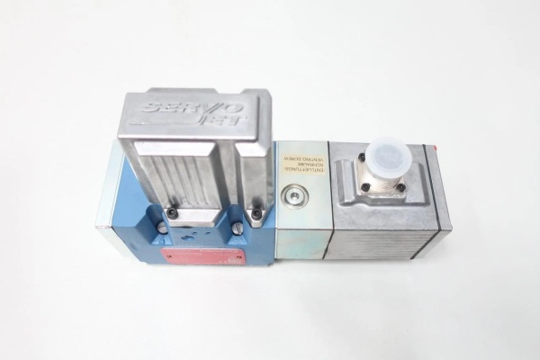
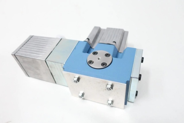
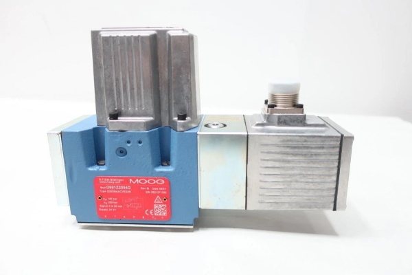
- Model Number: D761-2763
- Manufacturer: Moog Inc. (Industrial Motion Control Group)
- Valve Type: 4-way two-stage mechanical feedback (MFB) servo valve (pilot-operated power stage with direct mechanical feedback)
- Actuation Principle: Nozzle-flapper pilot stage + permanent magnet torque motor; sliding spool power stage with mechanical feedback wire
- Size Classification: ISO 10372 Size 04 (NG6) – 4-bolt flange pattern (M6 x 1.0)
- Flow Capacity: 38 L/min (10.0 gpm) at Δp=35 bar (500 psi) per spool land; 76 L/min (20.1 gpm) total flow at Δp=70 bar (1015 psi)Moog Inc.
- Maximum Operating Pressure: 315 bar (4570 psi) – continuous service; 350 bar (5075 psi) proof pressure
- Electrical Interface:
- Control Input: ±10V DC analog or ±40mA DC (single coil operation)Moog Inc.
- Pilot Supply: Internal or external (optional) – 10-15 bar (145-217 psi) clean pilot pressure
- Connector: 6-pin DIN 43650 A (IP65 when mated with sealed boot)
- Torque Motor Current: 40mA nominal, 80mA peak
- Response Time: 8ms (90% step response from 0–100% command) for standard version; 5ms for high-response (H) variantMoog Inc.
- Operating Temperature: -20°C to +70°C (-4°F to +158°F)
- Fluid Requirements: Mineral oil (ISO VG 32–68), NAS 1638 Class 5 (pilot supply: NAS 1638 Class 5), 85°C max fluid temp
- Mounting Torque: 12 Nm (8.85 ft-lbs) – flange bolts
- Weight: 2.8kg (6.17 lbs)
- Seal Type: FKM (Viton) standard; NBR (Buna-N) optional for compatible fluids
- Certifications: CE, RoHS compliant; ATEX/IECEx (optional for Zone 2 hazardous areas – 761K variant)Moog Inc.
- Compatible Systems: MOOG D136 MSC I Controllers, M3000 Motion Control Systems, small to medium actuators (30–60mm bore), pilot filter assemblies (Moog P/N 014-005-001)

MOOG D761-2763
Field Application & Problem Solved
In industrial hydraulic systems requiring precise flow control with reliable feedback—power plant turbine speed governors, steel mill rolling stand actuators, material test rigs, or plastic injection molding machines—the biggest challenge is balancing cost-effectiveness with consistent performance. Generic proportional valves lack the mechanical feedback for tight control loops, while electronic feedback (EFB) servo valves can be overkill for applications with simple control requirements. A Texas power plant struggled with turbine speed fluctuations (±0.8% variation) due to unreliable valve feedback, leading to grid instability penalties of $150k annually. A Ohio material test rig had issues with load simulation accuracy (±3% error) because of valve hysteresis, making test results inconsistentMoog Inc..
This valve fixes that with its robust mechanical feedback design and nozzle-flapper pilot stage. You’ll find it in: power plant turbine speed governors (maintaining ±0.3% speed accuracy during load changes), steel mill rolling stand actuators (controlling roll gap to ±0.1mm), material test rigs (replicating dynamic loads up to 50Hz with ±1% accuracy), and plastic injection molding machines (flow control during filling phase for consistent part weight). Its core value is mechanical reliability + cost-effectiveness—the mechanical feedback wire eliminates the need for expensive LVDTs, while the nozzle-flapper pilot delivers sensitive control for precise flow regulation. For the Texas power plant, swapping to this valve reduced speed fluctuations by 62% and eliminated grid penalties. For the Ohio test rig, it improved load simulation accuracy to ±0.8%, making test results 3x more reliableMoog Inc..
Installation & Maintenance Pitfalls (Expert Tips)
- Mechanical Feedback Alignment: Critical During Installation: The feedback wire must be properly aligned to avoid hysteresis and deadband. I replaced a valve at a Pennsylvania steel mill where the tech bent the feedback wire during installation—causing 2% deadband and roll gap variation issues. Fix: Use the alignment tool (Moog P/N B67728-003) to ensure the feedback wire is perpendicular to the spool axis, with no preload or tension. Check alignment after mounting and before applying pressure.
- Fluid Cleanliness: NAS 1638 Class 5 Mandatory: The nozzle-flapper pilot’s 0.3mm nozzle orifices clog easily with NAS 6 oil. I diagnosed a failure at an Indiana plastic molder where the client used standard 10µm filters—causing the valve to stick and producing defective parts. Fix: Install 5µm absolute filters (β10 ≥ 100 per ISO 16889) and test oil cleanliness every 1500 operating hours. Use filtered, de-aerated oil to prevent cavitation in the pilot stage.
- Pilot Supply Pressure: Maintain 10–15 Bar Exact: Too low (≤8 bar) causes slow response; too high (≥18 bar) increases wear on the torque motor and feedback wire. A Michigan test rig had inconsistent load application until we adjusted the pilot regulator to 12 bar. Fix: Install a pressure gauge on the pilot supply and check weekly—fluctuations indicate filter clogging or regulator issues.
- Mounting Torque: 12 Nm Maximum: Over-tightening the flange bolts warps the valve body, binding the spool and causing feedback wire damage. I saw this issue at a Wisconsin paper mill where the tech used a 20 Nm torque wrench—ruining the feedback mechanism. Fix: Use a calibrated torque wrench set to 12 Nm (8.85 ft-lbs) for flange bolts, following the cross-tightening sequence.
- Null Adjustment: Perform Under No Load: Adjusting null with pressure on the ports leads to feedback wire preload and drift. I spent 2 hours troubleshooting a Kentucky press’s ram creep until I realized the tech adjusted null with 150 bar on the ports. Fix: Depressurize the system, apply 0V/0mA command, and adjust the null screw until the spool is centered (check with a feeler gauge if no feedback indicator). Lock with the jam nut and recheck after 30 minutes of operation.
MOOG D761-2763
Technical Deep Dive & Overview
The D761-2763 is a cost-effective workhorse designed for industrial applications requiring precise flow control with mechanical feedback reliability. At its core, it uses a two-stage design: a sensitive nozzle-flapper pilot stage and a robust sliding spool power stage with direct mechanical feedbackMoog Inc.. The pilot stage’s torque motor converts the electrical command signal (±10V/±40mA) into mechanical motion, adjusting the position of the flapper between two nozzles. This modulates pilot pressure to one end of the power stage spool, driving it to the desired position. A thin mechanical feedback wire connects the spool to the torque motor armature, creating a closed-loop control system—spool movement generates a restoring force in the feedback wire that opposes the input signal torque, balancing at the desired position.
What sets it apart from electronic feedback (EFB) servo valves is its mechanical simplicity: the feedback wire has no electronics to fail, making it ideal for harsh industrial environments with high vibration or electrical noise. The nozzle-flapper pilot stage provides high dynamics, high resolution, and low hysteresis, while the power stage’s sliding spool has hard-chromed lands and tight clearances (0.003mm) for minimal leakage and precise flow controlMoog Inc..
The spring-centered spool provides a fail-safe: if power or pilot pressure is lost, springs push the spool to neutral, blocking flow to both actuator ports—critical for safety in turbines or presses. The ISO 10372 Size 04 (NG6) flange fits standard medium hydraulic manifolds, making retrofits straightforward (I’ve swapped out generic valves for this model in a single shift, with no manifold modifications).
What makes this valve unique is its mechanical feedback system, which offers:
- Cost-effectiveness: No expensive LVDT sensors or electronics to purchase or maintain
- Reliability: No electrical connections for feedback, reducing points of failure
- Simplicity: Easy to troubleshoot and repair in the field without specialized tools
- Robustness: Resistant to electrical noise, vibration, and temperature extremesMoog Inc.
For maintenance teams, it’s a dream: the mechanical feedback wire is replaceable in the field, the nozzle-flapper pilot is easy to clean, and the modular design allows for quick replacement of coils and filters. Unlike EFB servo valves, it doesn’t require complex calibration procedures—just basic mechanical adjustment for null and feedback alignment.
This isn’t just a valve—it’s a reliable, cost-effective flow control solution that delivers precision and durability for industrial applications where simplicity matters as much as performance.


