
Description
Key Technical Specifications
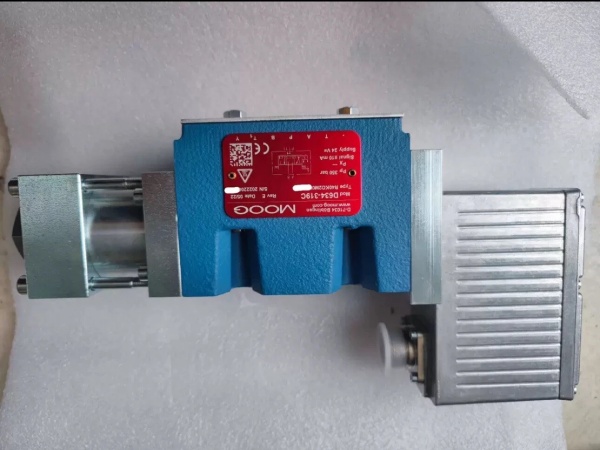
- Model Number: D061-9321
- Manufacturer: Moog Inc. (Industrial Motion Control Group)
- Valve Type: 4-way two-stage servo valve (pilot-operated power stage)
- Actuation Principle: Nozzle-flapper pilot stage + permanent magnet torque motor; sliding spool power stage
- Size Classification: ISO 4401 Size 05 (NG10) – 4-bolt flange pattern (M8 x 1.25)
- Flow Capacity: 120 L/min (31.7 gpm) at Δp=70 bar (1015 psi)
- Maximum Operating Pressure: 350 bar (5075 psi) – continuous service
- Electrical Interface:
- Control Input: ±4-20mA DC or ±10V DC (switch-selectable, 12-bit resolution)
- Pilot Supply: 10-15 bar (145-217 psi) clean pilot pressure (filtered separately)
- Connector: 10-pin DIN 43650 A (IP65 when mated with sealed boot)
- Torque Motor Current: 80mA nominal, 150mA peak
- Response Time: 5ms (90% step response from 0–100% command)
- Operating Temperature: -20°C to +70°C (-4°F to +158°F)
- Fluid Requirements: Mineral oil (ISO VG 32–68), NAS 1638 Class 6 (pilot supply: NAS 1638 Class 5), 85°C max fluid temp
- Mounting Torque: 25 Nm (18.4 ft-lbs) – flange bolts
- Weight: 4.8kg (10.6 lbs)
- Seal Type: Viton (standard); Buna-N optional for compatible fluids
- Certifications: CE, RoHS compliant; ATEX/IECEx (optional for Zone 2 hazardous areas)
- Compatible Systems: MOOG D136 MSC I Controllers, M3000 Motion Control Systems, large actuators (60–120mm bore), pilot filter assemblies (Moog P/N 014-005-001)

MOOG D634-319C
Field Application & Problem Solved
In high-pressure, high-flow industrial hydraulic systems—power plant turbine governors, steel mill hot rolling stands, 200+ ton hydraulic presses—the biggest nightmare is balancing raw power with precision. Single-stage valves can’t handle the flow demands, while generic two-stage valves suffer from pilot stage failures (clogged nozzles, torque motor drift) that cause catastrophic downtime. A coal-fired power plant in Indiana lost $400k annually to unplanned outages when their generic valves’ pilot nozzles clogged, tripping turbine governors. A Pennsylvania steel mill struggled with 0.1mm roll gap variation (leading to sheet thickness defects) because their valves lacked consistent dynamic response.
This valve fixes that with its robust two-stage design optimized for harsh industrial conditions. You’ll find it in: power plant turbine speed governors (maintaining ±0.5% speed accuracy during load changes), steel mill hot rolling stand actuators (controlling roll gap to ±0.05mm), heavy-duty test rigs (replicating dynamic loads up to 100Hz), and large forging presses (ram position control at 400mm/s with ±0.1mm precision). Its core value is power + precision + reliability—the nozzle-flapper pilot delivers sensitive control, the power stage handles high flow, and the separate pilot supply (with dedicated filtration) reduces contamination risks. For the Indiana power plant, swapping to this valve cut turbine-related downtime by 80% and eliminated nozzle clogging failures. For the Pennsylvania mill, it reduced roll gap variation by 50%, cutting sheet metal scrap by $220k/year.
Installation & Maintenance Pitfalls (Expert Tips)
- Pilot Supply Filtration: NAS 1638 Class 5 Is Non-Negotiable: Rookies use the same filtration for pilot and main fluid, but the nozzle-flapper pilot’s 0.1mm nozzle orifices clog with NAS 6 oil. I replaced three valves at a Kentucky power plant where the client skipped a dedicated pilot filter—each failure caused a 6-hour turbine outage. Fix: Install a dedicated 5µm pilot filter (β10 ≥ 100 per ISO 16889) and change it every 3000 operating hours. Never tap pilot supply from unfiltered main lines.
- Pilot Pressure: Maintain 10–15 Bar Exact: Too low (≤8 bar) causes slow response; too high (≥18 bar) wears the torque motor. A Ohio steel mill’s rolling stand had 0.2mm gap variation until we adjusted the pilot regulator to 12 bar. Fix: Install a pressure gauge on the pilot supply and check weekly—fluctuations indicate filter clogging or regulator issues.
- Mounting Alignment: Keep the Valve Parallel to the Actuator: Misalignment (≥1°) causes spool binding and premature wear. A Michigan test rig’s valve failed after 12 months until we shimmed the flange to align with the actuator’s hydraulic lines. Fix: Use a straightedge to verify parallelism between the valve and manifold—no gaps or twists.
- Electrical Shielding: Double-Shielded Cable for Control Signals: Unshielded or single-shielded cables pick up EMI from generators or VFDs, causing torque motor drift. A Tennessee power plant’s turbine speed fluctuated by ±1% until we replaced the control cable with double-shielded twisted-pair, grounded only at the controller. Keep control cables 30cm away from power cables.
- Null Adjustment: Do It Cold, Under No Load: Adjusting null when the valve is hot or under pressure leads to drift when the system cools. I spent 4 hours troubleshooting a West Virginia press’s ram creep until I realized the tech adjusted null with 250 bar on the ports. Fix: Depressurize the system, let the valve cool to ambient temp, apply 0V/4mA command, and adjust the null screw until feedback reads 0V (±0.01V). Lock with the jam nut and recheck after 30 minutes of operation.
MOOG D634-319C
Technical Deep Dive & Overview
The D061-9321 is a workhorse designed for the most demanding industrial hydraulic systems—where high pressure, high flow, and precision can’t be compromised. At its core, it uses a two-stage design: a sensitive nozzle-flapper pilot stage and a robust sliding spool power stage. The pilot stage’s torque motor converts the electrical command signal (±4-20mA/±10V) into mechanical motion, adjusting the position of the flapper between two nozzles. This modulates pilot pressure to one end of the power stage spool, driving it to the desired position. An internal LVDT provides spool position feedback to the controller, closing the loop and ensuring accuracy.
What sets it apart from generic two-stage valves is its ruggedized pilot stage: the nozzles are hard-chromed (0.5µm surface finish) to resist wear, and the torque motor uses rare-earth magnets for consistent force output over 20,000+ hours. The separate pilot supply requirement (10–15 bar) is a feature, not a flaw—by filtering the pilot fluid separately, you protect the sensitive nozzle-flapper from contamination that would disable lesser valves. The power stage’s sliding spool has hard-chromed lands and tight clearances (0.004mm) for minimal leakage and precise flow control.
The spring-centered spool provides a fail-safe: if power or pilot pressure is lost, springs push the spool to neutral, blocking flow to both actuator ports—critical for safety in turbines or presses. The ISO 4401 Size 05 flange fits standard large hydraulic manifolds, making retrofits straightforward (I’ve swapped out generic valves for this model in a single shift, with no manifold modifications).
For maintenance teams, it’s predictable: most failures stem from poor pilot supply filtration or electrical noise, so a strict maintenance schedule (pilot filter changes, oil analysis, cable inspection) keeps it running. Unlike single-stage valves, it doesn’t sacrifice flow for precision—120 L/min moves large actuators fast, while the two-stage design ensures the sensitivity needed for tight control. It’s not just a valve—it’s the backbone of reliable, high-performance hydraulic control in power generation, steel production, and heavy manufacturing.


