
Description
Hard-Numbers: Technical Specifications
-
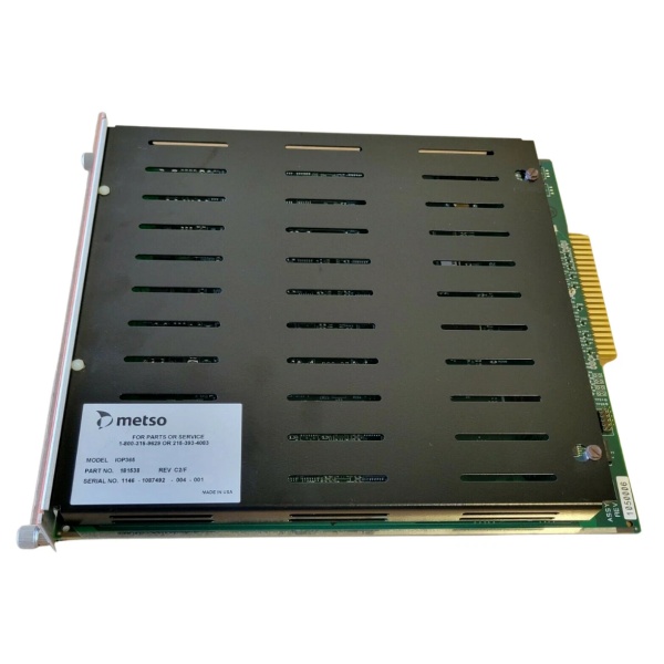
Function: Optical Bus Extender Module (BEM)
-
Link Speed: 160 MBaud serial data over fiber
-
Maximum Distance: 2000 meters (6560 feet)
-
Optical Wavelength: 1300 nm (multimode fiber)
-
Fiber Type: 62.5/125 µm multimode fiber optic cable
-
Cable Part Numbers: CON062-LLLL (2-fiber), CON064-LLLL (4-fiber recommended for redundancy)
-
Connector Type: ST type (optical transceivers), Tx/Rx pairs
-
I/O Capacity: Up to 60 I/O modules per remote location; up to 255 unique I/O addresses per DPU
-
Bus Loading: One BEM = one I/O module load on local bus
-
Power Requirements: 24V DC @ 0.5A (12W max)
-
Operating Temperature: 0°C to 60°C
-
Humidity: 0% to 90% RH non-condensing
-
Isolation: 1500V field-to-system isolation
-
EMI/RFI: Meets SAMA PMC33.1 specs; designed to IEC 801-2 (8,000V static)
-
Failover Time: Milliseconds (momentary interruption only)
-
Dimensions: 176 mm × 88.5 mm × 212 mm (H × W × D) – standard maxPAC module
-
Weight: 0.54 kg (module); 5 lbs (shipping)
-
Compatibility: DPU4A, DPU4B, DPU4E (NOT compatible with DPU3, DPU4, or controller file models)
-
Redundancy: Supports dual redundant fiber links with automatic switchover

The Real-World Problem It Solves
Running analog signals from field transmitters in a paper machine wet end or mining concentrator back to a central control room creates ground loops, signal degradation, and massive cable costs. The IOP371 drops onto the DPU’s I/O backplane, converts parallel bus data to 160 MBaud serial, and shoots it over fiber to a remote cabinet up to 2 km away. Remote I/O modules there behave exactly as if they were local—same scan rates, same diagnostics, no protocol translation.
Where you’ll typically find it:
-
Paper machine wet end sections where I/O cabinets sit next to the stock chests, 800 meters from the control room
-
Mining concentrators with the MCC in a separate building from the DPU rack
-
Lime kiln temperature monitoring with I/O at the kiln and DPU in the central control room
This module eliminates voltage drop in analog signals, reduces cable tray loading, and lets you put I/O where the process is—not where the control room happens to be.
Hardware Architecture & Under-the-Hood Logic
The IOP371 functions as a transparent bus bridge—the DPU has no idea the I/O is remote. The module handles parallel-to-serial conversion, error checking, and optical transmission without protocol changes.
Signal flow and processing logic:
-
Local Bus Interface: The IOP371 plugs into the DPU’s parallel I/O bus (Model IOP bus). It appears as one I/O module load to the DPU bus master.
-
Parallel-to-Serial Conversion: A dedicated chipset converts 8-bit parallel data to 160 MBaud serial stream. Error checking bits are appended for transmission integrity.
-
Optical Transmission: The transmitter converts TTL-level serial data to 1300 nm optical signals. Two independent transceivers support Link 1 and Link 2 for redundancy.
-
Remote Regeneration: At the remote end, a paired IOP371 receives the optical signal, converts back to parallel, and regenerates the exact I/O bus timing on the remote backplane.
-
Automatic Failover: On power-up, Link 1 is active. If the receiver detects loss of signal or errors, it switches to Link 2 within milliseconds—fast enough that the DPU sees only a momentary I/O interruption. A Form C relay contact and front-panel LED indicate failover events.
-
CPLD Control: Complex Programmable Logic Devices manage the link state machine, watchdog timing, and failover logic. A hardware watchdog monitors CPLD operation and forces safe state if internal faults occur.
METSO IOP365
Field Service Pitfalls: What Rookies Get Wrong
Mixing Single and Redundant Fiber Cables
The IOP371 supports redundant links, but if you run both fibers in the same conduit and a backhoe cuts it, you lose both links. Metso explicitly requires physically separate cable routes for Link 1 and Link 2.
-
Field Rule: Always use CON064-LLLL (4-fiber cable) and route Link 1 and Link 2 in separate trays or conduits. The two extra fibers in each cable are spares—don’t use them as primary links. If the “Link 2” LED never lights during commissioning, you’ve probably swapped Tx and Rx at one end—fiber is not Ethernet; direction matters.
Ignoring the Distance-Derating Curve
At 2000 meters, the optical delay limits you to 4-8 I/O modules depending on type. Exceed this and the DPU times out during I/O scans, causing “I/O Not Responding” faults that look like module failures.
-
Quick Fix: Consult the derating table before adding remote I/O. At 500 meters, you can have 12 analog inputs; at 2000 meters, only 4. If you’re at the limit and need one more module, either move the remote rack closer or add a second BEM pair to create a separate remote bus—don’t just keep adding modules and hope.
Forgetting the Y-Cable in Redundant DPU Configurations
When redundant DPUs (primary/secondary) both need to reach the same remote I/O, you need a special Y-cable (Part No. 04374) to split the I/O bus to two local BEMs. Without it, only one DPU can see the remote I/O, defeating redundancy.
-
Field Rule: In redundant DPU setups, verify the Y-cable is installed between the DPUs and local BEMs. Check jumper W3 on both local BEMs—installed for redundant mode, removed for common mode. If the secondary DPU shows all remote I/O as “Bad Quality” while the primary is fine, you’ve either got a missing Y-cable or mismatched jumper settings.


