
Description
Hard-Numbers: Technical Specifications
-
Input Channels: 8 isolated channels (configurable per channel)
-
Input Types: 4-20mA, 0-20mA, ±20mA, 0-10V, ±10V, 1-5V (jumper/software selectable)
-
Isolation: 1500V AC channel-to-channel and field-to-system
-
Input Impedance: 250Ω (current mode), >1MΩ (voltage mode), >10MΩ (some configurations)
-
A/D Converter: 16-bit sigma-delta with oversampling digital filter
-
Resolution: 0.0015% of span (16-bit)
-
Accuracy: ±0.1% of span (typical at 25°C)
-
Update Rate: 50ms per channel (configurable)
-
Sampling Rate: 1000 Hz or faster (depending on configuration)
-
Normal Mode Rejection: Excellent 50/60 Hz rejection via digital filter
-
Burnout Detection: <3.6mA (open loop detection)
-
Surge Protection: 4kV
-
Power Supply: 24V DC nominal (20-30V DC range)
-
Power Consumption: 3.5W typical
-
Operating Temperature: -20°C to +60°C (some sources indicate 0°C to 60°C)
-
Storage Temperature: -40°C to +85°C
-
Humidity: 5% to 95% RH non-condensing
-
Enclosure Rating: IP20 (standard), IP65 (enhanced variants)
-
Mounting: DIN rail (EN 60715) or VME rack (depending on chassis)
-
Dimensions: 176 mm × 88.5 mm × 212 mm (H × W × D) – typical maxPAC module size
-
Weight: 1.3 kg (module)
-
Compatibility: Metso DNA, maxDNA, maxPAC DPU4A/4B/4E controllers

The Real-World Problem It Solves
Pulp mills, mining operations, and process plants need reliable analog signal conditioning that won’t ground-loop or drift over time. The IOP365 drops onto a DIN rail or VME chassis and handles the dirty work—converting 4-20mA from field transmitters, RTDs from motor bearings, or thermocouples from kiln zones into clean digital data for the DPU. The 1500V isolation keeps ground faults in the field from frying the control system, while auto-calibration compensates for temperature drift in harsh environments.
Where you’ll typically find it:
-
Paper machine stock preparation lines measuring consistency and flow transmitters
-
Mining crushing and grinding circuits monitoring vibration and temperature
-
Lime kiln temperature zones using Type K thermocouples with cold junction compensation
This module bridges the gap between raw field signals and the DCS, handling isolation, linearization, and diagnostics without eating DPU processing cycles.
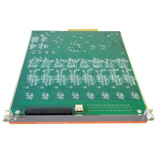
Hardware Architecture & Under-the-Hood Logic
The IOP365 functions as a distributed I/O processor—not just a dumb A/D converter. It handles signal conditioning, linearization, and diagnostics locally, then feeds digital data to the DPU via the I/O bus.
Signal flow and processing logic:
-
Input Selection: Eight channels accept 4-20mA, voltage, or (in some variants) RTD/thermocouple signals. Jumpers or software configure each channel independently.
-
Isolation Barrier: Each channel passes through 1500V AC isolation using optical relays and DC/DC converters. Field-side power is completely isolated from logic-side power.
-
Sigma-Delta Conversion: A dedicated 16-bit sigma-delta A/D converter oversamples each input, providing inherent 50/60 Hz noise rejection through digital filtering.
-
Microcontroller Processing: An onboard microcontroller manages channel multiplexing, gain selection, and linearization. It executes open-wire detection (burnout) and overrange checking immediately after each conversion.
-
Auto-Calibration: On power-up and periodically during operation, the module self-calibrates against internal precision references. This compensates for temperature drift and aging—critical in paper mills where ambient hits 60°C.
-
Bus Interface: A bus FPGA handles communication with the DPU via the maxPAC I/O bus. The FPGA program loads from flash on power-up. Data transfers on demand from the DPU.
-
Diagnostics: The microcontroller runs continuous self-tests. Faults are reported via blinking “Active” LED codes (e.g., 0x12 for A/D send fault, 0x14 for calibration failure) and status bits to the DPU.
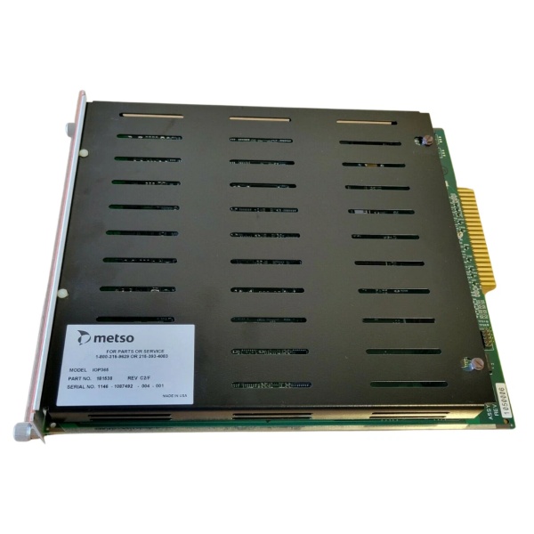
METSO IOP365
Field Service Pitfalls: What Rookies Get Wrong
Assuming All IOP365s Are Identical
Metso shipped the IOP365 in multiple hardware revisions (C2/F, etc.) and functional variants. Some handle analog inputs, others handle serial communications. The part number suffix determines function.
-
Field Rule: Check the revision label before swapping. An IOP365 Rev C2/F from a serial comm application won’t work as an analog input replacement even if it fits the slot. Verify the configuration jumpers (W2, W3, W6) match the original—W2 selects common vs. redundant I/O, W3 selects 50/60 Hz filtering, W6 selects Model 564 compatibility mode vs. maxPAC native mode.
Ignoring the Cold Junction Compensation Requirement
When configured for thermocouples, the IOP365 requires external thermistors (Metso P/N 074566) installed at the terminal blocks for cold junction compensation. Without them, TC readings drift with ambient temperature changes.
-
Quick Fix: If TC readings are off by 5-10°C but the transmitter checks out, look for missing or failed CJC thermistors. These are installed in connectors P4 and P5 at the front of the module. When using remote termination panels, the thermistors must be relocated to the remote terminations—not left on the module. Document this during commissioning; future techs won’t know otherwise.
Mixing 50 Hz and 60 Hz Filter Settings
The sigma-delta A/D provides excellent noise rejection, but only if the filter frequency matches the local power grid. A 50 Hz setting in a 60 Hz plant (or vice versa) results in unstable readings that look like process noise.
-
Field Rule: Verify jumper W3 before applying power. In North America, remove W3 for 60 Hz. In Europe/Asia, install W3 for 50 Hz. If readings drift or oscillate by ±0.5% of span, check this jumper first—it’s faster than swapping the module.


