
Description
Hard-Numbers: Technical Specifications
- Motor Power: 15.0 kW (20 HP)
- Rated Mains Voltage: 3 × 400/500 V AC, 50/60 Hz (permissible range: 3 × 380-480 V ±15%)
- Rated Output Current: 32.0 A (at 400 V), 25.6 A (at 500 V)
- Max Output Frequency: 0-599 Hz (extended range up to 1000 Hz with servo control)
- DC-Bus Voltage: 455-775 V (for 400/480 V versions)
- Enclosure Rating: IP20 (indoor cabinet installation only)
- Weight: 6.84 kg (approximately 15 lbs)
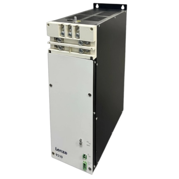
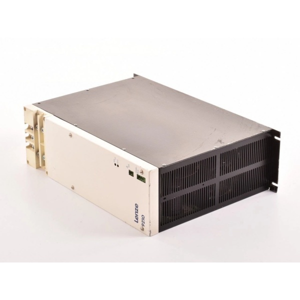
- Dimensions: 140 mm × 325 mm × 199 mm (W × H × D)
- Ambient Temperature: -10°C to +50°C (IP20)
- Storage Temperature: -25°C to +70°C
- Control Voltage: 24 V DC external supply required
- Digital I/O: 8 inputs / 4 outputs (freely programmable)
- Analog I/O: 2 inputs / 2 outputs (configurable voltage/current)
- Communication: CANopen onboard; optional EtherCAT, EtherNet/IP, POWERLINK, PROFIBUS, PROFINET
- Encoder Support: TTL incremental, SinCos incremental/absolute, SSI absolute (via 15-pin Sub-D multi-encoder input)
- Resolver Input: Sub-D 9-pin connector (for motor feedback)
- Axis Bus: 3-wire cross-communication for multi-axis synchronization
- Brake Chopper: Integrated (supports external brake resistor for regenerative braking)
- Safety Function: Optional Safe Torque Off (STO)
- Max Baud Rate: 1000 kbps (for fieldbus communication)
- Isolation: Control circuits optically isolated from power circuits
- Protection: Overcurrent, overvoltage, undervoltage, motor stall, I²t motor monitoring, phase failure

Lenze 9215
The Real-World Problem It Solves
High-speed packaging lines and material handling systems need rapid acceleration, precise positioning, and tight multi-axis synchronization without throwing your entire process into chaos when one axis lags. Standard VFDs choke under dynamic loads and lack the communication infrastructure for coordinated motion.
The 8400 TopLine brings servo-grade performance to the frequency inverter world with integrated multi-encoder inputs and an axis bus that synchronizes multiple drives with minimal wiring. It handles vector control with or without feedback, supports synchronous motors, and gives you integrated positioning control right out of the box.
Where you’ll typically find it:
- Rotary indexing tables and pick-and-place units in packaging machinery
- Warehouse automated storage and retrieval systems (AS/RS)
- Traveling drives and hoist systems in intralogistics
- Conveyor systems requiring multi-motor speed synchronization
- Form-fill-seal machines with web tension control
The bottom line: It bridges the gap between VFDs and full servo systems, giving you dynamic motion control, multi-axis synchronization, and encoder-based precision without the cost or complexity of dedicated servo drives for every axis.
Hardware Architecture & Under-the-Hood Logic
This unit sits between your three-phase mains and the motor, converting variable frequency AC to control motor speed with servo-grade dynamics. Unlike basic VFDs, it includes dedicated encoder processing, resolver support, and an axis bus communication interface for multi-drive coordination.
- Three-phase AC (400-500 V) enters through the power terminals and passes through the integrated EMC filter.
- The input rectifier converts AC to DC, charging the intermediate DC-bus capacitor bank.
- The IGBT inverter stage switches DC to variable-frequency AC using PWM modulation at selectable switching frequencies.
- Control algorithms (V/f, sensorless vector, or full servo with feedback) process motor current and voltage feedback in real-time.
- For servo applications, the multi-encoder input (15-pin Sub-D) reads encoder signals from TTL, SinCos, or SSI devices and feeds position data back to the control loop.
- The resolver input (9-pin Sub-D) provides an alternative feedback path for motors with resolver feedback.
- The axis bus (3-wire) communicates with other 8400 TopLine units for electrical shafting, ratio-based synchronization, and coordinated motion.
- Fieldbus communication (CANopen onboard; others via option modules) exchanges data with PLCs or higher-level controllers.
- Digital I/O (8 inputs, 4 outputs) handles discrete control signals—start/stop, jog, fault reset, programmable functions.
- Analog I/O (2 inputs, 2 outputs) provides speed reference or process variable control via 0-10V or 4-20mA signals.
- During deceleration, the integrated brake chopper dumps excess regenerative energy into an external brake resistor (internal resistor is not included on this power rating).
- The 24V DC control power supply runs the logic, display, and communication circuits independently of mains power.
The architecture splits power and control: power handling stays in the IGBT stage and DC-bus, while the control electronics manage feedback, communication, and motion algorithms separately for better noise immunity and reliability.
Lenze 9215
Field Service Pitfalls: What Rookies Get Wrong
Multi-Encoder Wiring Confusion
The 15-pin Sub-D multi-encoder connector supports TTL, SinCos, SSI, and other encoder types—all on the same pins with different wiring configurations. Techs frequently wire a SinCos encoder using the TTL pinout and wonder why they get erratic position feedback or no signal at all.
Field Rule: Identify your encoder type FIRST before wiring. The Lenze manual has separate pinout diagrams for TTL incremental, SinCos incremental/absolute, and SSI absolute encoders. Cross-referencing the wrong diagram will fry your encoder or feed garbage back to the drive. Use the E84A hardware manual page 240 (Encoder Connection) for the exact pinout matching your encoder.
Axis Bus Termination Issues
When daisy-chaining multiple 8400 TopLine units on the axis bus for electrical shafting, technicians forget to terminate the last unit in the chain properly. The result: random communication faults, synchronization errors, and axes that occasionally drop out of coordinated motion.
Quick Fix: The axis bus requires termination resistors at both ends of the bus chain. Most units have built-in termination that’s enabled via DIP switch or jumper. Verify the first unit’s termination is ON and the last unit’s termination is ON. All intermediate units must have termination OFF. If you’re seeing axis bus faults, check termination before replacing drives.
Ignoring the 24V External Supply Requirement
The 8400 TopLine requires an external 24V DC supply for the control electronics, separate from the mains power. New techs sometimes assume the drive generates its own control voltage, skip the 24V connection, and get a dead display or erratic behavior when the unit powers up.
Field Rule: The external 24V supply is mandatory for proper operation. Connect to the X40 terminal (24V and GND) and verify voltage before enabling the drive. This supply powers the display, keypad, communication interfaces, and control logic. Mains alone will not make this unit functional.
Brake Resistor Sizing for Regenerative Braking
You’re running high-inertia loads with frequent deceleration cycles, but you’re undersizing the external brake resistor or skipping it entirely. The DC-bus voltage spikes during braking, triggering overvoltage faults and shutting down your process.
Field Rule: Calculate the required brake resistor based on your deceleration energy per cycle and cycle frequency. The 15kW TopLine has an integrated brake chopper but requires an external resistor for regenerative applications. Use Lenze’s brake resistor sizing formula or selection chart in the manual. Never short the brake resistor terminals—you’ll destroy the chopper transistor instantly.
Resolver vs. Encoder Selection Confusion
You’re trying to run a motor with resolver feedback but wired the multi-encoder connector as if it were a SinCos encoder. Or vice versa. The drive can’t read the feedback and throws motor-related faults immediately.
Quick Fix: Know your motor before you power up. Resolver feedback goes to the dedicated 9-pin Sub-D resolver input (X6). Encoder feedback (TTL, SinCos, SSI) goes to the 15-pin multi-encoder input (X8). These are separate, isolated channels. Don’t try to force a resolver signal into the encoder input or vice versa.
Analog Input Scaling Mismatches
Your PLC is sending a 4-20mA speed reference, but the drive is configured for 0-10V input. Or the scaling parameters (C0050, C0051) are set wrong. The motor runs at the wrong speed or doesn’t respond properly to your process control.
Field Rule: Verify your analog input configuration matches your control signal. For 4-20mA current input, set the appropriate parameter for current mode and configure the scaling (minimum/maximum values correspond to 4mA/20mA). Use a multimeter to measure the actual signal at the drive terminals while commanding different speeds from your PLC—never assume the PLC output is correct without verification.
CANopen Node Address Conflicts
You’ve got multiple drives on the CANopen bus, but they all shipped with default node address 1. The bus goes berserk with duplicate addresses, communication timeouts, and drives that randomly ignore commands.
Field Rule: Every node on the CANopen bus must have a unique address. Configure node addresses via parameter C0113 before connecting to the network. Document the address mapping for each drive. If you’re replacing a drive, copy the old drive’s address—don’t default to 1 and assume it’s fine.
Forgetting Motor Data Parameters
After a drive replacement, techs power up without entering the motor’s rated current, voltage, and speed parameters. The drive runs the motor with default settings, which can cause overheating, insufficient torque, or outright stalling under load.
Field Rule: The motor nameplate is your bible. Enter motor rated voltage (C0002), rated current (C0003), rated speed (C0004), and rated power into the new drive before attempting any operation. If you don’t have the nameplate, measure motor resistance and consult the motor manufacturer’s data. Running with wrong motor parameters kills both motors and drives.
Ground Loops from Improper Shielding
You’ve got long motor cables and encoder cables running parallel to power cables, with shields grounded at both ends. Noise injects into your encoder feedback and analog signals, causing erratic motion and random faults that defy logical troubleshooting.
Field Rule: Ground cable shields at the drive end only—never at both ends. Use properly shielded encoder and motor cables. Separate low-voltage control cables from power cables by at least 200mm (8 inches). Follow the EMC installation guidelines in the Lenze manual. If you’re fighting noise issues, check your grounding scheme first—most problems trace back to improper shielding or ground loops.
STO Safety Function Bypass
The optional STO (Safe Torque Off) function is wired to your safety relay, but someone bypassed it to “get production running” during a faulted interlock. Now you’ve got a hazardous motion situation with the safety system defeated.
Field Rule: Never bypass STO or any safety interlock. The STO function is designed to remove torque from the motor in a fail-safe manner. If the safety circuit is tripping, fix the root cause—the safety sensors, wiring, or controller—not by shorting terminals. Bypassing safety functions is a liability nightmare waiting to happen.


