
Description
Hard-Numbers: Technical Specifications
Temperature Measurement Performance
- Measurement Range: Probe-dependent (typically -80°C to +450°C for standard probes)
- Accuracy: ±0.05°C to ±0.5°C (probe-dependent)
- Resolution: 0.01°C (16-bit ADC)
- Stability: <0.3°C over 100 seconds at 1 Hz (2σ)
- Long-term Drift: ±0.05°C over 5 years (FGA-0172K series typical)
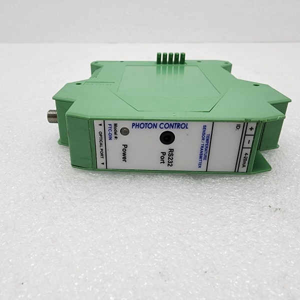
Communication Interfaces
- Analog Output: 4-20 mA (16-bit DAC), isolated
- Digital Communication: Modbus® RTU via RS-485 or RS-232
- Sampling Rate: Up to 30 Hz (probe and converter dependent)
- Probe Connection: SSMA fiber optic connector (FC/PC or UPC polish depending on probe)
Electrical Specifications
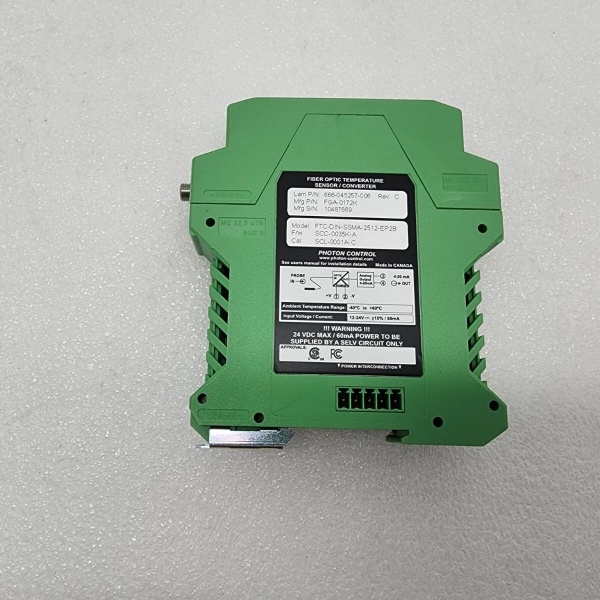
- Power Supply: 24 VDC ±20% (19.2-28.8 VDC)
- Power Consumption: <2 W typical (excluding load)
- Input Power Isolation: 500V isolation between input and circuitry
Mechanical Specifications
- Mounting: 35 mm DIN-rail mount
- Dimensions: 114 mm H × 22.5 mm W × 98 mm D
- Weight: ~0.2 kg (0.44 lbs)
- Connector Type: SSMA fiber optic receptacle
- Enclosure: Aluminum enclosure, IP20 rating
Environmental Specifications
- Operating Temperature (Converter): -20°C to +60°C
- Storage Temperature: -40°C to +85°C
- EMI Immunity: Complete immunity (all-dielectric measurement)
- Cleanroom Compatibility: Non-contaminating, suitable for Class 1-100,000 cleanrooms
Safety and Certifications
- Compliance: CE, RoHS, semiconductor equipment standards
- Isolation: 500V electrical isolation at measurement point
LAM 666-045257-006
The Real-World Problem It Solves
Semiconductor manufacturing chambers (plasma etch, CVD, PVD) generate intense electromagnetic fields—RF plasma at 13.56 MHz, microwave sources, and high-voltage DC bias. Conventional thermocouples or RTDs act as antennas, picking up EMI that corrupts temperature readings or causes ground loops. Worse, metallic sensors introduce contamination risk and create electrical paths that can interfere with sensitive plasma processes. The FGA-0172K uses all-dielectric fiber optic technology with a GaAs crystal sensing element—no electrical connections at the measurement point, complete EMI immunity, and zero contamination risk. When plasma RF noise causes other sensors to drift 10°C or more, fiber optics deliver rock-steady readings within ±0.1°C.
Where you’ll typically find it:
- Lam Research etch chambers (TCP, 2300, Vector series)
- Plasma-enhanced CVD and ALD reactors
- High-power RF sputtering systems
- Induction heating coils with electromagnetic interference
- Wafer chuck and electrostatic chuck temperature monitoring
- Cluster tool temperature profiling systems
Bottom line: Fiber optic temperature measurement eliminates the EMI vs. accuracy trade-off—you get sub-degree precision even when 10 kW of RF power is blasting through the chamber. The all-dielectric sensor won’t short your process, won’t contaminate your wafers, and won’t drift when the plasma ignites.
Hardware Architecture & Under-the-Hood Logic
The FGA-0172K is a single-channel fiber optic temperature converter based on gallium arsenide (GaAs) semiconductor bandgap fluorescence technology. It interrogates a remote fiber optic probe containing a GaAs crystal at the tip, converts the optical signal to an electrical temperature reading, and provides analog and digital outputs for integration with semiconductor equipment control systems.
-
GaAs Fluorescence Sensing Principle: The measurement principle relies on the temperature-dependent bandgap characteristics of gallium arsenide. A white LED in the converter launches light down the fiber optic cable to the GaAs crystal at the probe tip. As the crystal’s temperature changes, its bandgap shifts, altering the fluorescence spectrum and decay time. The crystal reflects unabsorbed light back through the same fiber. The converter analyzes the fluorescence characteristics—specifically, the wavelength at which absorption shifts—and correlates this to temperature using a calibrated lookup curve. This relationship is intrinsic to GaAs physics, providing absolute temperature measurement without periodic recalibration.
-
Optical Interrogation Circuitry: The converter contains a white LED light source (typically with 5+ year lifetime) and a spectrometer or filtered photodetector for analyzing returned light. The LED modulates at a specific frequency to distinguish measurement light from ambient interference. Reflected light from the probe passes through optical filters that isolate the fluorescence band before reaching the photodetector. The photodetector converts optical intensity to an electrical signal proportional to temperature. Advanced signal processing extracts the fluorescence decay constant or spectral shift, rejecting noise from LED intensity variations or fiber attenuation.
-
16-Bit ADC and Analog Output: A 16-bit digital-to-analog converter (DAC) generates the 4-20 mA output. At 16-bit resolution, the analog output provides 65,536 discrete steps across the configured temperature range—for a 0-500°C range, that’s ~0.0076°C per step. The output is isolated from the converter’s internal electronics and power supply, preventing ground loops between the measurement system and the semiconductor tool controller.
-
Modbus Digital Interface: The converter implements Modbus RTU protocol over RS-485 for digital communication. The tool’s host controller can read temperature values, configure measurement parameters, and retrieve diagnostic information via Modbus registers. Typical registers include:
- Current Temperature: 32-bit floating-point value in °C
- Probe Status: Connected, disconnected, or fault condition
- LED Intensity: Relative light level for predictive maintenance
- Diagnostic Flags: Low light, communication fault, out-of-range
-
Diagnostics and Health Monitoring: The FGA-0172K includes continuous self-diagnostics to detect degradation before it affects accuracy:
- LED Health Monitoring: Tracks emitted light intensity over time. A gradual decline indicates LED aging; a sharp drop may indicate LED failure.
- Fiber Continuity Check: Verifies that light is returning from the probe. A loss of return signal indicates broken fiber or disconnected probe.
- Signal Quality Monitoring: Evaluates the fluorescence signal-to-noise ratio. Poor signal quality may indicate probe contamination or fiber damage.
- Temperature Validation: Cross-checks measured temperature against internal reference for gross error detection.
-
Power Supply and Isolation: The converter operates from 24 VDC with internal regulation and filtering. The input is protected against overvoltage, reverse polarity, and transients. Critical isolation is provided between:
- Power Input to Measurement Circuitry: 500V galvanic isolation prevents ground loops from the tool’s power system.
- Analog Output to Ground: Isolated output eliminates differential mode noise when connected to PLC or tool controller inputs.
- Digital Interface to Ground: RS-485 transceiver is isolated, preventing ground paths through communication cables.
-
Probe Configuration Flexibility: The FTC-DIN-SSMA-2512-EP2B designation indicates compatibility with SSMA-connector fiber optic probes. The converter supports various probe types:
- Contact Probes: GaAs crystal bonded to a metal tip for surface contact measurement.
- Immersion Probes: Crystal enclosed in protective sheath for gas or liquid temperature measurement.
- Air/Gas Probes: Open-tip configuration for non-contact air temperature.Probe length can range from 0.5 meters to 10+ meters, with different fiber core sizes (200 μm, 400 μm, 600 μm) for trade-offs between signal strength and flexibility.
LAM 666-045257-006
Field Service Pitfalls: What Rookies Get Wrong
Using Metallic Probe Adapters Near Plasma Sources
Techs use metallic mounting brackets or adapters to hold the fiber optic probe near RF plasma coils or microwave sources. The metal acts as an antenna, picking up EMI and radiating it toward the measurement point. While the fiber itself is immune, the metal bracket can capacitively couple noise into the GaAs crystal housing or create local heating from induced currents. This causes temperature drift or erratic readings during plasma ignition.
- Field Rule: Use non-conductive mounting hardware for all probe fixtures near EMI sources. PEEK, PTFE, or ceramic brackets provide mechanical support without creating electrical paths. Keep metallic fasteners at least 30 cm from high-field regions. If metal mounting is unavoidable, ground the bracket to the chamber’s equipotential ground plane—not to the converter’s signal ground.
Confusing SSMA Connector Polish Types
The SSMA connector on the FTC-DIN-SSMA-2512-EP2B must match the probe’s connector polish. Rookies mix UPC (Ultra Physical Contact) and PC (Physical Contact) polished connectors or mismatch polish angles. UPC connectors have a slightly curved surface for optimal back-reflection, while PC connectors are flat. Mismatching causes poor optical contact, signal loss up to 3-6 dB, and erratic temperature readings or complete communication failure.
- Quick Fix: Verify connector polish type on both converter and probe before installation. UPC-UPC and PC-PC are correct pairings; UPC-PC is wrong. Inspect the connector ferrule under magnification for contamination or scratches. Clean with 99% isopropyl alcohol and lint-free wipes before mating. Never force a connector—if it doesn’t thread smoothly, 终止 and recheck alignment.
Ignoring LED Lifetime and Planning for Replacement
The white LED in the FGA-0172K has a finite lifespan—typically 5+ years at continuous operation. Techs assume the converter will work indefinitely without maintenance, never monitoring LED intensity trends in the Modbus diagnostics. As the LED ages, its output declines gradually. Initially, temperature accuracy degrades by 0.1°C, then 0.5°C, eventually causing measurement failure when light intensity falls below the detection threshold.
- Field Rule: Track LED intensity in Modbus register during routine maintenance. Establish a baseline when the converter is new. If intensity drops by more than 20% from baseline, plan for LED replacement or converter refurbishment. Most vendors offer refurbishment services that replace the LED and recalibrate the unit at a fraction of new-unit cost. For critical chambers, keep a spare converter on hand and swap it out proactively every 4-5 years.
Mishandling Fiber Optic Cables—Exceeding Minimum Bend Radius
Fiber optic probes are fragile—techs bend them around tight corners or route them through sharp edges during installation. Exceeding the minimum bend radius causes micro-cracks in the fiber core, leading to light loss, increased attenuation, and eventual fiber breakage. Symptoms start as intermittent temperature dropouts (signal loss when equipment vibrates) and progress to complete failure.
- Field Rule: Maintain minimum bend radius specified for the fiber—typically 25-30 mm for 600 μm core fibers, 20 mm for 400 μm. Use protective conduit or spiral wrap in high-traffic areas. Route fibers away from moving parts, pinch points, and sharp metal edges. Document cable routing in as-built drawings for future reference. If a fiber breaks, the repair is fusion splicing—field-serviceable but requires specialized equipment and training.
Forgetting to Configure Modbus Baud Rate and Parity
The FGA-0172K ships with default Modbus settings (typically 9600 baud, 8 data bits, no parity, 1 终止 bit). New engineers wire the converter to a semiconductor tool controller with mismatched communication parameters. The host controller can’t read temperature values or gets garbage data, causing the tool to fault out on “temperature sensor communication failure” during power-up.
- Quick Fix: During commissioning, verify Modbus settings on both converter and host controller match. Common configurations:
- Baud Rate: 9600 or 19200 bps
- Data Bits: 8
- Parity: None
- Stop Bits: 1
- Device Address: 1-247 (must be unique on the RS-485 bus)Test communication with Modbus polling software before integrating with the tool controller. Document settings in the system configuration file.
Neglecting to Verify Calibration with Reference Temperature
Fiber optic probes with GaAs crystals have inherent calibration stability—they don’t drift like thermocouples. However, the converter’s electronics or the probe’s optical coupling can degrade over time. Rookies trust the reading blindly, never cross-checking with a reference thermometer during maintenance. A 2°C drift goes unnoticed for months, causing process variation that affects wafer yield or etch uniformity.
- Field Rule: Annually verify calibration against a traceable reference thermometer (NIST-traceable platinum RTD or thermistor). Place the reference probe and fiber probe adjacent in a stable temperature environment (calibration bath or dry block). Compare readings across the operating range—room temperature, 100°C, 200°C. If deviation exceeds ±0.5°C, return the converter and probe for recalibration. For critical processes, perform quarterly spot checks at process temperature.
Overloading the RS-485 Bus with Too Many Devices
The FGA-0172K’s Modbus RS-485 interface shares a bus with other devices—tool controllers, pressure sensors, valve controllers. Engineers daisy-chain more than 32 devices or exceed total bus capacitance (2000 pF max). This causes signal reflections, data corruption, or intermittent communication failures that appear as random temperature sensor dropouts during operation.
- Field Rule: Count devices on the RS-485 bus—keep under 32 units per segment. Use termination resistors (120Ω) at both ends of the bus. For long cable runs (>100 meters), reduce baud rate to 9600 bps to compensate for capacitance. Measure bus capacitance with an LCR meter during commissioning—if over 1500 pF, shorten cable runs or add bus repeaters. Document network topology in the equipment manual.
Commercial Availability & Pricing Note
Please note: The listed price is for reference only and is not binding. Final pricing and terms are subject to negotiation based on current market conditions and availability.


