
Description
Hard-Numbers: Technical Specifications
- Bus Standard: VME (A24/D16 or A32/D32, jumper-configurable)
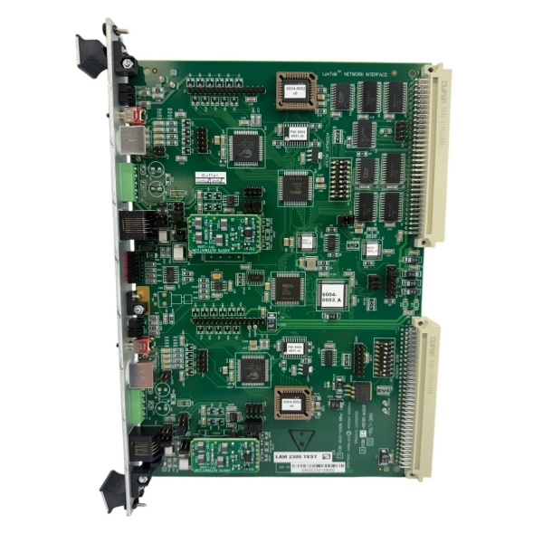
- Fieldbus Protocol: LonTalk (ANSI/CEA-709.1 compliant)
- Transceiver Type: FTT-10A Free Topology (differential twisted-pair)
- Data Rate: 78 kbps nominal
- Max Nodes per Channel: 64 nodes (theoretical max 32,385 per domain with routers)
- Isolation Rating: 500V galvanic isolation between LonWorks port and VME bus
- Operating Temperature: 0°C to +55°C (cabinet-derated above 45°C)
- Storage Temperature: -40°C to +85°C
- Power Supply: +5V DC from VME backplane or external +24V DC field power
- Power Draw: ~5W typical under full load
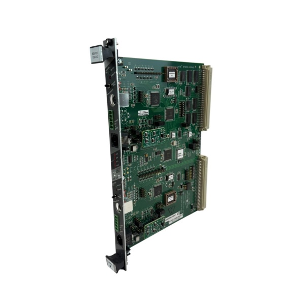
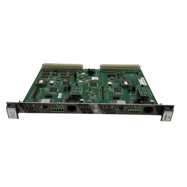
- Form Factor: 6U VME card (233.35mm × 160mm), DIN 41612 connector
- Network Variables: Up to 62 NVs per device
LAM 605-707109-012
The Real-World Problem It Solves
Multi-chamber etch systems have dozens of subsystems—vacuum pumps, MFCs, RF generators, pressure controllers—all needing coordinated control. Point-to-point wiring from a central PLC creates a cable harness nightmare, ground loops, and nightmare troubleshooting when one valve misbehaves at 2 AM. This board puts every subsystem on a single twisted-pair LonWorks fieldbus, slashing wiring and making diagnostics readable.
Where you’ll typically find it:
- Lam Research 2300 FLEX 45 Etch Chambers: Listed as “Lon Control B/D” in VME enclosures (853-042958-052), bridging CPU VME 7671 to distributed subsystems
- Multi-chamber cluster tools: Coordinating PM1/PM2/PM3 process modules via single network segment
- CVD/ALD reactors: Managing precursor delivery valves, thermal subsystems, and RF power on shared bus
Bottom line: When this board fails, your subsystems become islands—they can’t receive recipe commands or report status, and your tool goes down hard until the gateway is swapped.
Hardware Architecture & Under-the-Hood Logic
This board sits in the VME chassis as the LonWorks gateway. It has its own Neuron 3150 processor (3-core architecture: MAC, network, and application layers) plus VME bus interface logic in FPGA/CPLD. The board is fully isolated—500V between the LonWorks transceiver and the VME backplane, preventing ground loops from your field wiring from smoking the CPU.
- VME CPU writes to memory-mapped register on the board (e.g., address offset 0x1000 = “GasValve1_Setpoint”)
- FPGA decodes VME address/data bus, asserts DTACK, and passes the data to the Neuron processor’s application core
- Neuron application firmware updates network variable bound to that address (e.g., NV_nvoGasValvePosition)
- MAC core transmits LonTalk packet on the free topology network via FTT-10A transceiver
- Target subsystem (MFC, pump controller) receives packet, updates its local NV, and executes command
- Subsystem responds with status update, flows back through board to VME memory-mapped register where CPU reads it
- If packet fails or collision occurs, MAC core triggers automatic backoff and retry up to 3 times before setting error flag in status register
LAM 605-707109-012
Field Service Pitfalls: What Rookies Get Wrong
Ignoring LonWorks Network Termination
Techs connect the transceiver without checking for 120Ω termination resistors at both ends of the trunk. Missing terminators cause signal reflections—data pulses bounce off the open end and corrupt subsequent packets. You’ll see intermittent timeouts and random “neuron not responding” errors that clear when you wiggle wires, then come back at the worst possible time.
Field Rule: Measure resistance across the A/B wires with power off. Properly terminated network shows ~60Ω (two 120Ω resistors in parallel). If it reads open or infinite, you’re missing terminators. Install 120Ω resistors at both ends of the trunk, not at every drop.
Misconfiguring VME Address Space Jumpers
The board ships default A24/D16 addressing. Rookies plug it in without checking if another card in the chassis uses the same 16MB block. Two cards responding to the same address = bus contention, corrupted data, and mysterious CPU crashes during heavy I/O. System might boot fine then fault mid-recipe when both cards drive the bus simultaneously.
Field Rule: Document all VME address ranges before install. Set this board to an unused block—allocate 16KB minimum. Use a VME bus analyzer if available to scan occupied addresses. Label the selected range on the card edge for the next guy replacing it at 3 AM.
Mixing FTT-10A and Bus Transceivers on Same Segment
Free topology transceivers (FTT-10A) are designed for arbitrary wiring with built-in biasing. Bus transceivers (TPT/XF-1250) need dedicated terminators and linear topology. Mixing them creates marginal signal levels and excessive collision rates. Your network works until you add that one extra sensor, then everything goes sideways.
Quick Fix: Check every device’s transceiver type. Keep FTT-10A devices on their own segment. If you must mix, install a LonWorks router between the segments—routers isolate the physical layers while passing logical data. Don’t hope it works—test bindings with a network analyzer before go-live.
Failing to Update Neuron ID After Board Swap
Each board has a unique Neuron ID burned in EEPROM. Replace the board without reconfiguring the ID, and the network keeps talking to the dead board’s address. Your replacement powers up, LEDs look good, but it’s invisible—other nodes send commands into the void. Techs assume the replacement is DOA and order another, wasting two days.
Field Rule: Record the old board’s Neuron ID with a network management tool before pulling it. Configure the replacement to match that ID, or update network binding tables to reference the new ID. Keep a spare pre-configured with backup ID, test it monthly, and document all IDs in the maintenance log.
Commercial Availability & Pricing Note
Please note: The listed price is for reference only and is not binding. Final pricing and terms are subject to negotiation based on current market conditions and availability.


