
Description
Hard-Numbers: Technical Specifications
Optical Specifications
| Parameter | Value | Notes |
|---|---|---|
| Sensor Type | CMOS | High-resolution imaging sensor |
| Resolution | 5 Megapixels | 5MP effective pixel count |
| Maximum Frame Rate | 200 fps | Frames per second |
| Minimum Exposure Time | 1 microsecond | High-speed capture capability |
| Pixel Size | 2.2 x 2.2 microns | Pixel pitch |
| Sensitivity Range | ISO 200 to ISO 6400 | Adjustable sensitivity |
| Transmission Interface | GigE Vision | Gigabit Ethernet camera interface |
| Scan Distance | 110 mm | Working distance for line laser configuration |
Electrical and Physical Specifications
| Parameter | Value | Notes |
|---|---|---|
| Operating Voltage | 220 V AC | Mains supply voltage |
| Power Consumption | < 5W | Low power operation |
| Isolation Voltage | 2500V RMS | Electrical isolation rating |
| Weight | 0.88 lbs (0.4 kg) | [Confirmed from Radwell specification] |
| Dimensions | 110mm x 60mm x 30mm | Approximate dimensions [varies by source] |
| Housing Material | Aluminum alloy | Rigid construction |
| Protection Level | IP67 | Dust and water resistant |
Environmental Specifications
| Parameter | Value | Notes |
|---|---|---|
| Operating Temperature | -40°C to +70°C | Wide temperature range |
| Storage Temperature | -40°C to +85°C | Extended storage range |
| Humidity Range | 0% to 95% RH | Non-condensing |
| Output Frequency (High-Freq Variant) | 50 kHz | For specific high-frequency generator versions |
Data Verification Notes:
- The 5MP CMOS sensor and 200 fps specifications are consistently reported across multiple sources
- Weight of 0.88 lbs is confirmed from Radwell specification
- IP67 protection rating and 110mm scan distance are from specific sources
- Some sources describe this as a “high-frequency generator” (220V, 50kHz output) – this appears to refer to a different variant or application of the same model number. The optical specifications above are for the laser scanner/inspection variant
- Physical dimensions show variation across sources; use actual unit measurements for installation planning

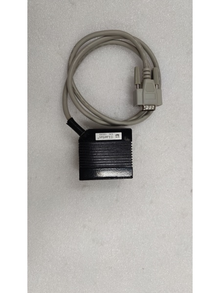
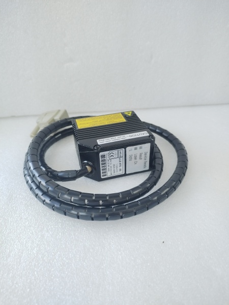
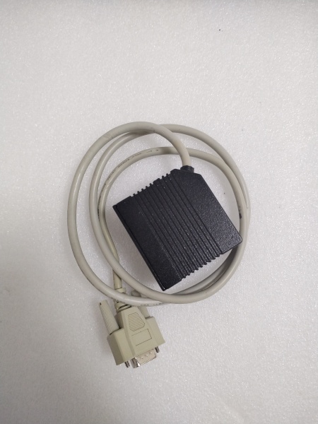
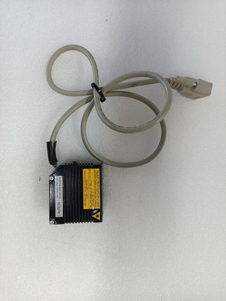
LAETUS LLS570-05
The Real-World Problem It Solves
High-speed production lines require real-time quality inspection to detect surface defects, printing errors, and packaging issues without slowing production. The LLS570-05 combines a high-resolution 5MP sensor with ultra-fast 200 fps capture rate, enabling detection of minute defects on fast-moving products. Its GigE Vision interface enables seamless integration into existing industrial networks, while the 1-microsecond minimum exposure captures clear images even on reflective or high-speed surfaces.
Where you’ll typically find it:
- Printing and packaging quality control lines for defect detection
- Pharmaceutical industry for label and packaging verification
- Food and beverage production for contamination detection
- Automotive parts inspection for surface quality control
- Logistics and sorting systems for barcode and character recognition
The bottom line: It delivers high-speed vision inspection capabilities that catch defects human operators would miss, ensuring product quality while maintaining production line throughput.
Hardware Architecture & Under-the-Hood Logic
The LLS570-05 uses a CMOS (Complementary Metal-Oxide-Semiconductor) image sensor with a global or rolling shutter architecture optimized for high-speed capture. The 5MP sensor provides 2592 x 1944 pixels at full resolution, with the ability to operate at reduced resolution to achieve the 200 fps maximum frame rate. The GigE Vision interface transmits image data over standard Ethernet using the GigE Vision protocol, ensuring compatibility with major machine vision software platforms.
Signal flow and operation:
- Front light emitter or line laser illuminates target surface
- CMOS sensor captures reflected light through optical lens system
- Analog pixel data converted to digital signals by onboard ADC
- Image processor applies correction algorithms (gain, exposure, white balance)
- GigE Vision interface transmits image data over Ethernet
- External PC or vision system receives and processes images
- Defect detection algorithms analyze image data in real-time
- Results sent to PLC or control system for quality decisions
- Defective products can be flagged or rejected automatically
Internal Components:
- 5MP CMOS sensor array (2592 x 1944 pixels)
- Optical lens assembly with adjustable focus
- Front light emitter or line laser module
- High-speed ADC (Analog-to-Digital Converter)
- FPGA or ASIC image processor
- Gigabit Ethernet PHY and controller
- Onboard memory buffer for frame capture
- Power supply circuit (AC/DC conversion)
- Environmental sealing for IP67 rating
Field Service Pitfalls: What Rookies Get Wrong
Incorrect Lighting Configuration
The front light emitter or line laser must be properly aligned with the target surface. Misaligned lighting causes glare, shadows, or uneven illumination that results in false defect detection or missed defects.
Field Rule: Use the manufacturer’s alignment procedure for the specific inspection task. Test with calibration targets before production runs. Adjust light intensity to avoid saturation while maintaining sufficient contrast.
Insufficient Network Bandwidth
At 200 fps with 5MP resolution, each frame generates significant data (approximately 15MB uncompressed). Standard 100Mbps Ethernet cannot sustain this data rate, causing dropped frames and missed inspections.
Quick Fix: Use dedicated Gigabit Ethernet (1000Mbps) switches with jumbo frame support. Ensure the PC network card and all intermediate switch ports support GigE Vision standards. Monitor network utilization during operation.
Exposure Time Misconfiguration
A 1-microsecond minimum exposure enables high-speed capture, but setting exposure too short reduces light available to the sensor, increasing noise. Too long exposure causes motion blur on fast-moving targets.
Field Rule: Calculate required exposure time based on target speed: Exposure (seconds) = Max allowable motion blur (mm) / Line speed (mm/s). Start with this calculation and adjust for lighting conditions. Use auto-exposure only if the process conditions are consistent.
Ignoring Environmental Conditions
IP67 rating protects against dust and water, but condensation can form inside the lens housing when operating in high-humidity environments with large temperature swings.
Quick Fix: Allow the unit to acclimate to ambient temperature before powering on. Use breather caps or desiccant in mounting areas with high humidity. Regularly inspect the front lens for fogging or contamination.
GigE Vision Configuration Errors
The GigE Vision interface requires proper IP configuration, packet size settings, and stream channel configuration. Incorrect settings prevent image acquisition or cause unstable operation.
Field Rule: Use the manufacturer’s configuration utility to set IP address, subnet mask, and gateway. Enable jumbo frames (9000 bytes) on all network devices. Verify stream parameters match camera capabilities in the vision software.
Calibration Drift
Mechanical vibration, thermal expansion, or physical impact can shift the optical alignment, causing measurement errors or missed defect detection zones.
Field Rule: Perform calibration checks weekly using known reference targets. Document calibration values and track trends. Realign the optics if calibration drift exceeds 0.1% of measurement tolerance.
LAETUS LLS570-05
Common Failure Modes and Troubleshooting
| Symptom | Possible Cause | Troubleshooting Steps |
|---|---|---|
| No image acquisition | Network disconnection, power failure | Check Ethernet link status, verify 220V AC power supply |
| Dropped frames at high speed | Insufficient network bandwidth | Verify GigE connection, check switch capability, reduce resolution |
| Dark or noisy images | Insufficient lighting, high ISO setting | Increase light intensity, lower ISO sensitivity |
| White or saturated images | Overexposure, light too bright | Reduce light intensity, decrease exposure time |
| Inconsistent measurements | Calibration drift, vibration | Recalibrate, check mounting stability, isolate from vibration |
| Communication timeout | IP address conflict, firewall blocking | Verify unique IP address, check firewall settings for GigE Vision port |
| Focusing issues | Lens contamination, impact damage | Clean front lens, check for physical damage, readjust focus |
Installation and Setup Procedure
Required Tools
- Torque screwdriver set (for mounting hardware)
- Network configuration software (manufacturer utility)
- GigE Vision compatible vision software
- Calibration targets (as specified by application)
- Multimeter (for power verification)
- Cat6 Ethernet cable (shielded preferred)
Installation Steps
-
Mounting the Scanner
- Select mounting location with stable vibration-free foundation
- Use mounting bracket compatible with 110mm x 60mm x 30mm dimensions
- Ensure adequate clearance for front light/laser emission
- Verify working distance (110mm typical) to target surface
- Tighten mounting bolts to specified torque
-
Electrical Connection
- Verify mains supply is 220V AC, 50/60Hz
- Connect power cable with proper grounding
- Use appropriate strain relief on cable entry
- Test power supply before full system startup
-
Network Configuration
- Connect Cat6 cable to GigE Vision port
- Use manufacturer utility to configure IP address
- Set subnet mask and gateway as required
- Ping camera from host PC to verify connectivity
- Enable jumbo frames on network switch and host NIC
-
Optical Alignment
- Power on the front light emitter or line laser
- Adjust mounting angle to illuminate target surface evenly
- Use calibration target to verify focus and field of view
- Adjust lens focus for sharp image at working distance
- Lock optical adjustment screws after alignment
-
Vision Software Setup
- Install GigE Vision driver for LLS570-05
- Configure camera parameters in vision software:
- Resolution (5MP or reduced for higher frame rate)
- Frame rate (up to 200 fps)
- Exposure time (minimum 1 microsecond)
- Gain and ISO setting (ISO 200-6400)
- Set up image acquisition triggers (external or software)
- Configure defect detection algorithms for application
-
Commissioning
- Run test with production samples
- Adjust lighting and exposure for defect visibility
- Verify frame rate meets production speed requirements
- Test defect detection accuracy with known good and bad samples
- Validate communication with PLC or control system
- Document final configuration parameters
Maintenance Schedule
| Maintenance Task | Frequency | Notes |
|---|---|---|
| Lens cleaning | Daily or per shift | Use compressed air and approved lens cleaner |
| Calibration verification | Weekly | Use reference target to check measurement accuracy |
| Mounting bolt inspection | Monthly | Check for loosening due to vibration |
| Network cable inspection | Monthly | Check for damage or loose connections |
| Air filter cleaning | Quarterly | If equipped with intake vents |
| Full calibration | Semi-annually | Complete optical and measurement calibration |
| Firmware update | As needed | Check manufacturer for updates |
Integration Considerations
Network Topology
- Use dedicated Gigabit Ethernet switch for vision cameras
- Isolate vision network from general plant network if possible
- Implement proper switch redundancy for critical applications
- Consider fiber optic cable for distances over 100 meters
PLC Integration
- Modbus TCP or PROFINET protocols typically supported
- Map defect results to PLC data blocks
- Configure alarm thresholds for automatic rejection
- Implement historical data logging for traceability
Software Compatibility
- Compatible with major machine vision software platforms:
- HALCON
- VisionPro
- Matrox Imaging Library (MIL)
- OpenCV with GigE Vision SDK
- Cognex VisionPro
- National Instruments Vision Development Module
Safety Warnings
- Laser Safety: If equipped with line laser, observe all laser safety precautions. Never look directly into the laser beam.
- Electrical Safety: 220V AC supply presents shock hazard. Ensure proper lockout/tagout before servicing.
- IP67 Sealing: Do not breach sealing unless performing authorized maintenance. Reinstall all gaskets and seals properly.
- Heat Generation: Ensure adequate ventilation for cooling. Do not obstruct heat dissipation surfaces.
- Moving Machinery: Install safety guards around inspection area if products are moving at high speed.
Technical Support and Resources
- LAETUS Official Documentation: Refer to manufacturer manuals for specific application details
- GigE Vision Standard: Reference AIA GigE Vision standard for compatibility information
- Integration Partners: Contact LAETUS for certified system integrators
- Application Engineering: Consult LAETUS application engineers for complex inspection tasks
IMPORTANT DATA RELIABILITY NOTICE:Multiple conflicting product descriptions exist for the LLS570-05 model number across various distributors and vendors. The specifications above represent the most commonly reported laser scanner/vision inspection variant (5MP CMOS sensor, 200 fps, GigE Vision interface). Some sources describe this model as a “high-frequency generator” (220V input, 50kHz output) or Foxboro I/O module. These appear to represent either different product variants, mislabeled listings, or alternative applications of the same base platform. For critical applications, verify exact specifications with the manufacturer or the specific unit’s nameplate and documentation before installation or procurement.


