
Description
Hard-Numbers: Technical Specifications
NOTE: Specifications below are primarily based on the KK67Y-YYYY-050 base model. Data for the specific -8.5-3000-B14 variant suffixes is inferred from standard naming conventions where exact documentation is unavailable.
- Continuous Power: 8.5 kW (base model variant)
- Input Voltage: 600 VAC, 3-phase (base model)
- Rated Current: 19.6 A
- Rated Speed: 3000 RPM (per -3000 suffix)
- Output Torque: ~27 Nm (calculated at 8.5kW/3000rpm)
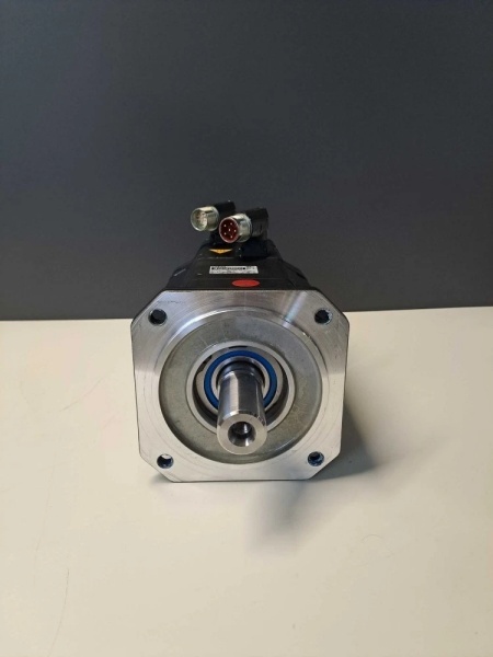
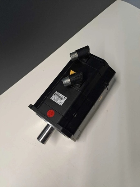
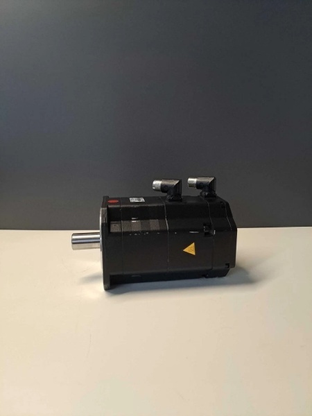
- Shaft Type: Spline shaft with integrated holding brake
- Feedback: Integrated resolver/encoder (exact type TBD per variant)
- Flange Type: B14 small flange (per -B14 suffix)
- Insulation Class: Class F
- Protection Rating: IP54 to IP65 (TBD per variant)
- Operating Temperature: 0°C to +45°C
- Weight: ~34 kg (75 lbs) for base model; B14 variant may differ

1FK7101-5AY81-1SH3-Z
The Real-World Problem It Solves
The KK67Y series servo motor is designed for applications that demand a combination of power, precision, and the safety of an integrated holding brake, all in a compact footprint with standardized B14 flange mounting. This simplifies installation and improves reliability in robot joints and automated machinery by eliminating the need for an external brake.
Where you’ll typically find it:
- Main joint drives on KUKA industrial robots (wrist, elbow, shoulder)
- Material handling systems with vertical loads requiring secure hold
- CNC and general machine tool axis drives
The bottom line: It’s a robust, self-contained servo solution that delivers power and control while maintaining position securely during power-off states—a key requirement for robotic safety and reliable automated processes.
Hardware Architecture & Under-the-Hood Logic
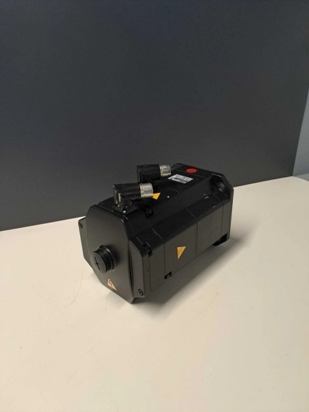
The KK67Y-YYYY-050-8.5-3000-B14 is a brushless permanent magnet synchronous motor. The rotor contains rare-earth magnets, and the stator windings generate a rotating magnetic field synchronized with the rotor position. A resolver or encoder provides precise position feedback for the drive controller. The integrated spring-applied holding brake is located on the non-drive end (NDE) and engages when de-energized.
Signal flow breaks down like this:
- Drive controller outputs three-phase variable-frequency, variable-voltage AC to the motor (U, V, W terminals).
- Rotor position is sensed by the integrated feedback device (resolver/encoder).
- Feedback signals return to the drive controller for precise commutation.
- Magnetic interaction between the stator’s rotating field and the rotor’s permanent magnets generates torque.
- The integrated brake coil is energized (typically 24VDC) to release the brake during operation.
- A KTY84 thermal sensor embedded in the stator windings monitors temperature for protection.
- Motor power and control cables connect via a rotatable connector for flexible routing.
- The B14 flange (small flange per IEC 60034-7 code IM3601) provides the mounting interface to the robot or machine.
Field Service Pitfalls: What Rookies Get Wrong
Brake Wiring Polarity ConfusionThe integrated brake is a 24VDC spring-applied type, but the coil has correct polarity for proper release. Techs sometimes reverse the polarity, causing the brake to drag or fail to release fully, leading to drive overcurrent faults and overheating.
- Field Rule: Always verify brake polarity against the motor nameplate or connection diagram. Use a multimeter to confirm the correct +/- assignment during installation. If the brake drags, the drive current will be abnormally high even at zero speed.
Resolver/Encoder Mismatch on ReplacementThe specific feedback device (resolver or encoder, and its exact signal characteristics like pole count or resolution) varies with the full part number suffix. A replacement motor with a different feedback type will not work with the existing drive configuration.
- Quick Fix: When ordering a replacement, always provide the complete model number, including all suffixes like -8.5-3000-B14. Verify the feedback device type and specifications on the replacement motor’s nameplate against the original. Never assume interchangeability based on the base model number alone.
B14 Flange Mounting ErrorsThe B14 is a small flange with specific bolt patterns and alignment dowel pin locations. Techs force-fit or misalign the mounting bolts, causing uneven stress on the flange, bearing misalignment, and premature bearing failure.
- Field Rule: Clean the mounting surface thoroughly. Verify that all alignment dowels are present and engage correctly. Tighten flange bolts in a star pattern to the manufacturer’s specified torque. Never rely on just two bolts to hold position—fully seat the flange before final torque.
Insufficient Thermal DeratingServing in a robot joint or an enclosed space can limit airflow. The motor’s nameplate rating assumes adequate cooling. Operating continuously near its rated power in a confined space will cause thermal trips.
- Field Rule: Assess the installation environment. If the motor is in a confined area with restricted ventilation, you must derate the continuous torque or provide forced cooling. Monitor motor temperature under real load conditions during commissioning.
Ignoring Specific Suffix CodesThe suffixes -8.5, -3000, and -B14 denote specific performance characteristics and mechanical interfaces. Substituting a motor with different suffix codes (e.g., different power, speed, or flange) will lead to performance mismatch or physical incompatibility.
- Quick Fix: The entire part number is your reference. Do not accept a substitute that only matches the base KK67Y-YYYY-050. Confirm every suffix character matches the original specification. Even small differences can indicate a critical variation.


