
Description
Hard-Numbers: Technical Specifications
- Safe Input Channels: 32 channels (24V DC)
- Safe Output Channels: 32 channels (24V DC, 2A max)
- Digital I/O Type: 24V DC, 2A per channel
- Rated Voltage: 24V DC (±10%)
- Power Consumption: 20W maximum
- Isolation Rating: 500V optical (I/O to control logic)
- Operating Temperature: 0°C to +50°C (32°F to +122°F)
- Enclosure Rating: IP20 (controller cabinet interior)
- Dimensions: 200mm × 120mm × 80mm (H×W×D)
- Weight: 0.5 kg (1.1 lb)
- Mounting: PC plug-in card via MFC3 backplane
- Update Rate: 1-4 ms (depends on controller load)
- LED Indicators: Power, Status, Fault, Communication (per channel group)
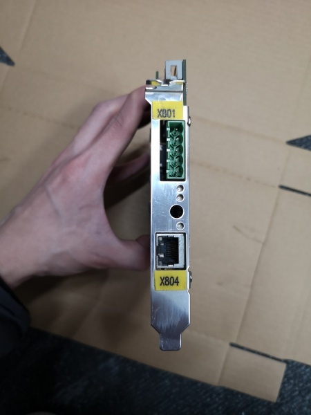
- Connectors: X4 (servo drive interface), X810 (MFC3 backplane connection)

KUKA DSE-IBSC33-1.40
The Real-World Problem It Solves
You need a centralized interface that manages safety-critical I/O signals while controlling servo modules, without requiring separate safety PLCs or external safety relays. The DSE-IBSC33 consolidates 64 channels of safe I/O with direct servo control capability, reducing component count and potential failure points in the safety architecture.
Where you’ll typically find it:
- KUKA KR C4 robot control cabinets
- Multi-axis robotic cell control systems
- Safety-critical automation cells requiring PL d/SIL 2 compliance
The bottom line: It’s the central nervous system for KR C4 I/O and servo control, integrating safety-rated inputs/outputs with drive interface logic without external safety controllers.
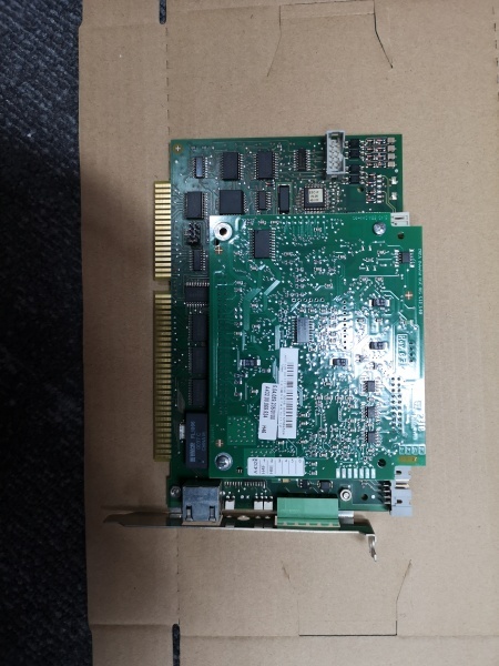
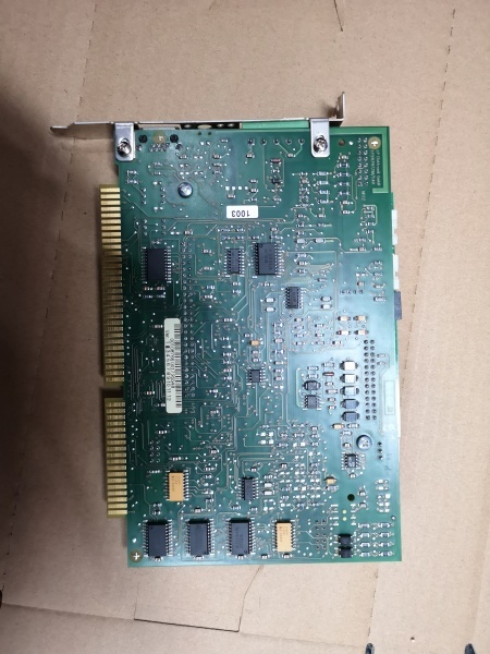
Hardware Architecture & Under-the-Hood Logic
This board is a multi-function interface card that plugs into the MFC3 (Multi-Function Card) backplane in the KR C4 controller. It combines safe I/O processing, servo module control, and safety logic interface in a single PC-compatible card. The board processes error and status information from servo modules while routing safe I/O signals through isolated channels.
Signal flow breaks down like this:
- Safe input signals (24V DC) enter through terminal blocks or safety circuits
- Input signals condition through opto-isolators for safety compliance
- Safe output signals route through protected output drivers to actuators
- Servo commands exchange via X4 connector to KSD servo drives
- Status and error data read from servo modules for fault processing
- Data exchanges with MFC3 through X810 backplane interface
- Safety logic integrates with CI3 safety circuit (ESC)
- LED indicators reflect real-time channel health and fault conditions
KUKA DSE-IBSC33-1.40
Field Service Pitfalls: What Rookies Get Wrong
Incorrect Safe I/O ConfigurationThe 32 inputs and 32 outputs are safety-rated and require specific configuration in the KUKA workVisual software. Techs treat them like standard digital I/O, then the safety circuit faults or fails to meet PL d/SIL 2 requirements during TÜV inspection.
- Field Rule: Configure each safe I/O channel in the safety project, not the standard I/O section. Verify safety function assignment and test with a deliberate fault condition (remove input signal) to confirm the controller enters safe state within the specified time.
Backplane Seating IssuesThe DSE-IBSC33 plugs into the MFC3 backplane, and poor contact causes intermittent communication faults. Techs rush the installation and don’t verify the card is fully seated, leading to random “DSE connection lost” alarms.
- Quick Fix: Press firmly until the card clicks into the backplane connector, then secure the mounting screws. Verify the green LED flashes steadily (indicates active connection). If the LED flickers or stays off, remove and reseat the card—don’t ignore the flicker.
Swapping Between KR C2 and KR C4 SystemsThe DSE-IBSC33-1.40 variant is specific to KR C4 controllers, while earlier variants fit KR C2. Techs pull a KR C2 card and plug it into a KR C4 cabinet, or vice versa, causing complete controller failure.
- Field Rule: Match the full part number including the suffix (1.40, 1.10, etc.). Verify compatibility against the controller manual’s PC slot assignment. Never assume interchangeability across controller generations—KR C2 and KR C4 use different backplane architectures.
Overloading Safe Output ChannelsEach safe output channel is rated for 2A maximum. Techs wire multiple solenoids or contactors in parallel to a single output, exceeding the rating and blowing the output driver.
- Quick Fix: Calculate load current per channel. If you’re driving more than 1.5A (derate for temperature and wiring losses), use an external contactor or relay. Measure actual current draw with a clamp meter during commissioning—nameplate values lie sometimes.
Ignoring Variant Suffix DifferencesThe “-1.40” suffix indicates specific hardware functionality and firmware version. Techs replace with a different suffix (e.g., -1.10) and the system fails to boot or faults on hardware mismatch.
- Field Rule: Always match the exact part number including the suffix. Suffix changes represent hardware revisions, firmware compatibility, or safety certification updates. If you can’t source the exact suffix, contact KUKA support—don’t attempt a cross-reference without authorization.


