
Description
Hard-Numbers: Technical Specifications
- Frame Size: 71 mm
- Continuous Torque: 4.0 Nm (35 in-lb)
- Peak Torque: 12.0 Nm (106 in-lb)
- Rated Speed: 6000 RPM
- Continuous Power: 2.5 kW (3.35 HP)
- Peak Power: 7.5 kW (10.0 HP)
- Voltage Constant: 95 V/kRPM
- Torque Constant: 1.25 Nm/A
- Resistance: 0.55 ohms (line-to-line)
- Inductance: 4.2 mH (line-to-line)
- Feedback: Absolute encoder (multi-turn, EnDat or Hiperface)
- Cooling: Natural convection (optionally forced air)
- Thermal Time Constant: 30 min
- Inertia: 2.8 kg·cm²
- Weight: 8.5 kg (18.7 lb)
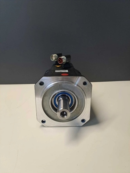
- Mounting: Flange 80 mm with 19 mm shaft diameter
- IP Rating: IP64 (shaft vertical), IP65 (optional)
- Holding Brake: Included in this variant (5AY81 indicates brake present)

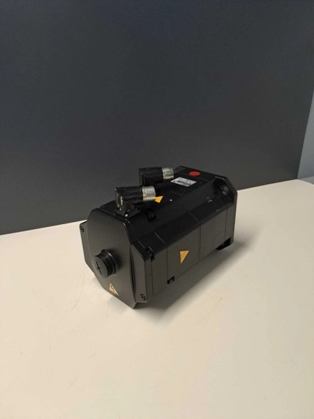
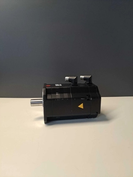
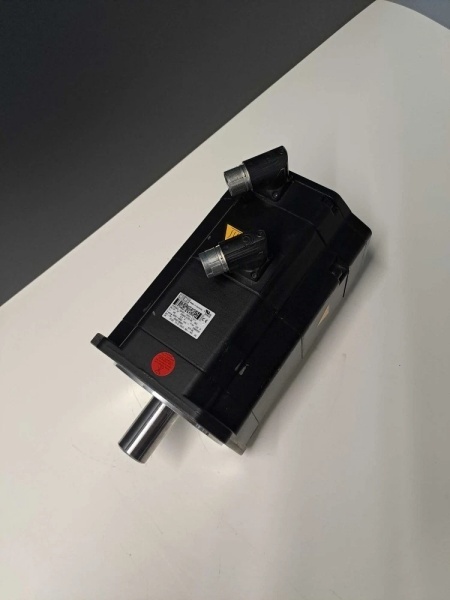
1FK7101-5AY81-1SH3-Z
The Real-World Problem It Solves
You need precise, repeatable motion with high dynamic response, and the application demands the motor hold its position securely when powered down. The 1FK7101 delivers 4.0 Nm continuous torque with integrated holding brake and absolute encoder, making it ideal for robot joints where gravity load retention and zero-reference homing are critical.
Where you’ll typically find it:
- KUKA robot joint drives (wrist and elbow axes)
- Pick-and-place units in high-speed assembly lines
- Tool changers and turret positioning on CNC machines
The bottom line: It’s a compact, high-performance servo motor with built-in position retention and absolute feedback—perfect for applications where zero homing and secure positioning are non-negotiable.
Hardware Architecture & Under-the-Hood Logic
This is a 6-pole brushless synchronous motor with rare-earth permanent magnets on the rotor. The stator windings generate a rotating magnetic field that drags the rotor into synchronism. The absolute encoder provides position feedback without requiring homing after power loss. The holding brake is a spring-applied, electrically-released disc brake on the non-drive end.
Signal flow breaks down like this:
- Drive outputs three-phase AC current to stator windings (U, V, W)
- Current vector aligns with rotor position via encoder feedback
- Magnetic interaction between stator field and rotor magnets produces torque
- Absolute encoder transmits position data via EnDat or Hiperface protocol
- Brake coil energizes to release brake when motor is enabled
- Thermal switch monitors stator winding temperature (opens at 155°C)
- Front shaft seal (IP64/IP65) protects bearings from contaminants
Field Service Pitfalls: What Rookies Get Wrong
Brake Wiring ConfusionThe brake has two wires, but techs confuse the voltage rating. Some variants are 24VDC, others use 48VDC or even 230VAC. Applying wrong voltage either doesn’t release the brake or burns out the coil instantly.
- Field Rule: Check the motor nameplate for brake voltage (B-Brake or similar). Verify with a multimeter on the brake terminals—measure coil resistance to confirm. 24VDC brakes typically read 20-30Ω; 48VDC read 80-120Ω. Never apply voltage without confirming.
Encoder Cable ShieldingTechs use non-shielded encoder cable or tie the shield incorrectly. The absolute encoder data corrupts intermittently, causing position drift or complete commutation failure. The encoder system is noise-sensitive.
- Quick Fix: Use shielded twisted-pair cable specified for the encoder protocol. Ground the shield at the controller end only—never both ends. If you’re seeing intermittent position faults, run a temporary shielded cable directly from motor to controller to verify the cable is the issue.
Ignoring Brake Release DelayThe brake takes 50-150ms to release after power is applied. Techs command motion immediately, causing the drive to fault on overcurrent as it tries to move against the engaged brake.
- Field Rule: Configure the drive parameter for brake release delay (typically 200-300ms to be safe). The drive should apply voltage to the brake, wait for release, then start the motion profile. Test it: command a slow move and verify the motor doesn’t surge when the brake releases.
Improper Phasing After RepairReplacing motor cables or the motor itself sometimes causes incorrect phasing of the encoder signals. The motor runs, but current draw is higher than normal and position error fluctuates.
- Field Rule: After any cable or motor replacement, run the drive’s phasing routine (commissioning mode). The drive will check encoder alignment and adjust parameters automatically. If phasing is wrong, you’ll burn out the motor or drive quickly—don’t skip this step.


