
Description
Hard-Numbers: Technical Specifications
-
Protocol Support: HART 7, Foundation Fieldbus H1, Profibus PA/DP, Modbus RTU (RS485), CAN Bus
-
Output Configurations: Up to 4 configurable I/O channels (current, pulse, frequency, status output, limit switch, control input depending on CG number)
-
Current Output: 4-20 mA active or passive, HART superimposed, load 0-500Ω (active), 0-1kΩ (passive)
-
Pulse/Frequency Output: 0-10 kHz, configurable as pulse (volume/mass totalizer) or frequency (flow rate)
-
Status Output: Solid-state relay, 30VDC/100mA max
-
Control Input: Digital input for zero calibration, totalizer reset, sensor standby, hold outputs
-
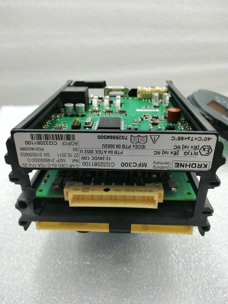
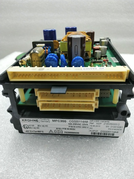
Power Supply: 100-230 VAC (-15/+10%), 50/60 Hz (standard); 12-24 VDC or 24 VAC/DC (optional)
-
Power Consumption: 22 VA (AC), 12 W (DC) typical
-
Operating Temperature: -40°C to +65°C (-40°F to +149°F) ambient
-
Storage Temperature: -50°C to +70°C (-58°F to +158°F)
-
Protection Class: IP66/67 (compact/field), IP65 (wall), IP20 (rack)
-
Housing Materials: Die-cast aluminum (polyurethane coated) or stainless steel 316L (1.4404) option
-
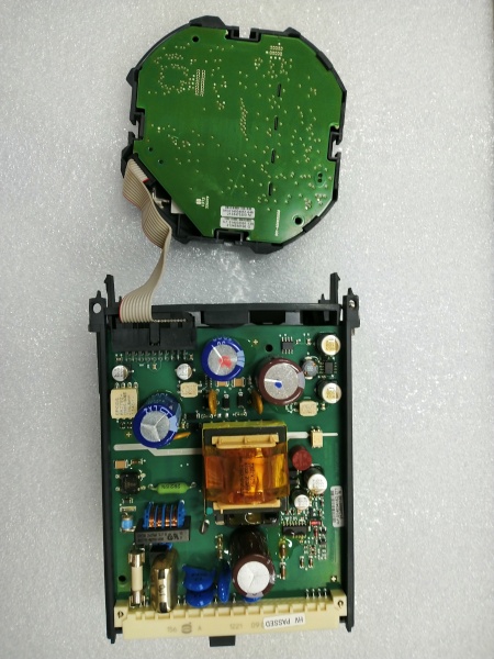
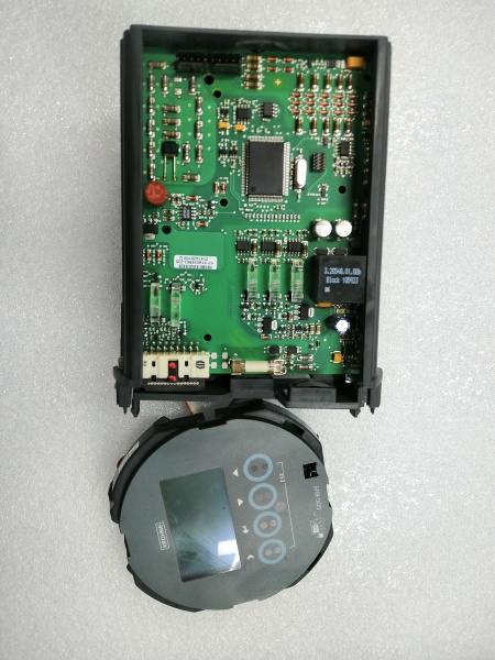
Display: Large backlit graphic LCD with 4 optical buttons (touchless operation)
-
Sensor Cable Length: Up to 300 m (1000 ft) for remote versions
-
Accuracy: ±0.4% of rate (mass flow), ±0.001 kg/l (density), ±0.5°C (temperature)
-
Response Time: <1 second for 63% step change (typical)
-
Measurement Update Rate: 10-100 Hz (configurable)
-
Cable Entries: M20×1.5 standard, ½” NPT or PF optional
-
Weight: 4.2 kg (compact), 5.7 kg (field), 2.4 kg (wall), 1.2 kg (rack)
-
Safety Certifications: ATEX, IECEx, FM, CSA (Class I Div 1/2), NEPSI, INMETRO (sensor-dependent)

KEOHNE MFC300
The Real-World Problem It Solves
Custody transfer and critical process control can’t afford measurement drift or calibration loss. A failed flow transmitter in a chemical batch or oil loading operation means lost product, EPA violations, or blown budgets. The MFC300 eliminates this nightmare by storing calibration parameters in dual redundant memory—if the electronics fail, swap the converter and the new unit inherits the exact same calibration without reconfiguration. It handles the messy reality of Coriolis measurement (temperature effects, two-phase flow, coating buildup) with advanced diagnostics that tell you if the meter is healthy or just pretending to be.
Where you’ll typically find it:
-
Custody transfer loading skids for refined products and chemicals
-
Chemical reactor feed control with density/concentration feedback loops
-
Food & beverage batching systems requiring hygienic stainless steel construction
-
Offshore platform allocation metering with tropicalized/environmental hardening
This converter keeps your mass flow measurement honest even when process conditions go sideways—no recalibration after swap-outs, no guesswork about meter health.
Hardware Architecture & Under-the-Hood Logic
The MFC300 isn’t just a 4-20mA generator—it’s a digital signal processor that runs the complete Coriolis algorithm stack. The split architecture separates the sensor (vibration measurement) from the converter (signal processing), allowing the converter to be mounted remotely up to 300 meters away in a climate-controlled shelter while the sensor lives in the pipe rack. The modular I/O concept uses a common hardware base with software-configurable output mappings.
Internal Signal Flow:
-
Sensor Interface: Receives low-level sine wave signals from the OPTIMASS sensor’s pickoff coils and drive coil feedback via dedicated field current/signal cable
-
Analog Front End: High-resolution ADCs sample the vibration phase shift (mass flow) and frequency (density) with temperature compensation from the Pt500 RTD
-
DSP Processing: Digital signal processor calculates mass flow rate, volumetric flow, density, and temperature using factory-stored calibration coefficients (tube stiffness, flow factors)
-
Dual Redundancy Storage: Calibration parameters stored in two independent non-volatile memory banks; automatic failover if one bank corrupts
-
Output Generation: D/A converters generate 4-20mA and pulse outputs; communication processors handle HART, Fieldbus, or Modbus protocols simultaneously
-
Diagnostic Engine: Continuously monitors drive coil current, pickoff signal amplitude, tube frequency, and zero stability; flags coating, erosion, or two-phase flow conditions
KEOHNE MFC300
Field Service Pitfalls: What Rookies Get Wrong
Assuming “Dual Redundancy” Means No Calibration Needed After Swap
The MFC300 stores calibration data redundantly, but only if the replacement unit is the same CG number (configuration code) and firmware version. Rookies grab any MFC300 off the shelf, install it, and wonder why the flow readings are 15% off even though the “calibration restored” message appeared.
-
Field Rule: Verify the CG number on the nameplate matches exactly before swapping. The CG code defines the I/O configuration, sensor type, and calibration curve. If you must use a different CG unit, you’ll need to perform a full wet calibration with known quantities or transfer the calibration data via the service tool. Check the “Sensor Serial Number” parameter after swap—it should match your physical sensor tag. If it doesn’t, the calibration coefficients are wrong.
Ignoring the 300m Cable Length Limit on Remote Mounts
The MFC300F field housing can mount 300m from the sensor, but that’s under ideal conditions (proper cable type, no intermediate splices, low EMI). Rookies run standard instrument cable through cable trays with VFD power cables and wonder why the signal drifts or drops out intermittently.
-
Quick Fix: Use KROHNE’s specified ARHE-C4 sensor cable only—it’s shielded, twisted-pair with proper impedance matching. Run it in dedicated conduit or cable tray segregated from motor power by 12 inches minimum. If you must exceed 100m, measure the loop resistance (should be <50Ω) and verify the drive coil voltage at the sensor end (should be >20Vpp). Check the “Pickoff Amplitude” diagnostic—if it’s trending down over time, you’ve got cable degradation or moisture ingress in the junction box.
Enabling All I/O Options Without Checking Power Budget
The MFC300 can be ordered with multiple I/O modules (4-20mA + pulse + status + control input), but each active output draws power from the internal supply. Rookies configure all outputs active on a 24VDC powered unit, then get “Undervoltage” alarms when the total load exceeds 12W.
-
Field Rule: Calculate your power budget before commissioning. Active 4-20mA outputs into 500Ω loads draw 24mA each (0.58W). Pulse outputs into low-impedance counters draw 50mA peak. If you’re running on 24VDC supply, limit yourself to two active current outputs plus one pulse output max. If you need more I/O, switch to 230VAC supply or use passive (loop-powered) current outputs. Monitor the “Supply Voltage” diagnostic in the display—if it drops below 20VDC under load, you’re over budget.


