
Description
Hard-Numbers: Technical Specifications
- Control Channels: Up to 8 independent thruster channels (configuration dependent)
- Input Voltage: 24VDC (18-36V range)
- Power Consumption: 25W nominal, 40W maximum
- Control Output: 4-20mA, ±10V analog, or CANopen (configurable per channel)
- Feedback Input: 4-20mA, 0-10V, or resolver feedback
- Analog Resolution: 12-bit (4096 steps)
- Update Rate: 10 ms (100 Hz) for control loops
- Isolation Rating: 1500V optical (channel to channel, channel to power)
- Operating Temperature: -15°C to +55°C (+5°F to +131°F)
- Enclosure Rating: IP66 (NEMA 4/4X)
- Mounting: Panel mount or DIN rail adapter available
- Dimensions: 300mm × 200mm × 120mm (H×W×D)
- Weight: 4.5 kg (9.9 lb)
- Communication Interface: CANopen, RS-485, Ethernet (variant dependent)
- LED Indicators: Power per channel, Communication, Fault, System Status

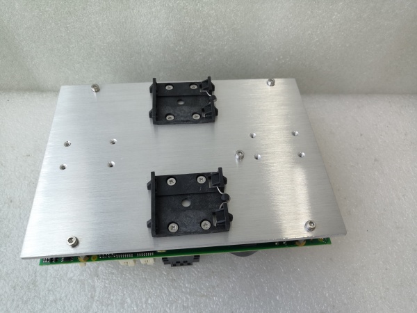
KONGSBERG RPC420 317114
The Real-World Problem It Solves
You need centralized control of multiple thrusters with precise feedback monitoring, but the bridge controls and drive systems are incompatible or physically separated. The RPC420 acts as the translation layer, converting bridge commands into propulsion drive inputs while providing real-time feedback on thruster status and performance.
Where you’ll typically find it:
- Dynamic positioning system central control cabinets
- Propulsion control rooms on offshore support vessels
- Thruster interface panels on drilling rigs and FPSO units
The bottom line: It bridges the gap between operator intent and mechanical thrust, giving you a single point of control and monitoring for multi-thruster systems without requiring custom interfaces for each drive manufacturer.
Hardware Architecture & Under-the-Hood Logic
This unit is essentially a multi-channel signal conditioner with integrated control logic and communication interfaces. Each channel processes command and feedback signals independently through isolated analog front-ends. The central processor manages channel-to-channel coordination and communication with the bridge control system.
Signal flow breaks down like this:
- Bridge commands enter via CANopen, RS-485, or Ethernet interface
- Command processor validates and scales signals for each thruster channel
- Isolated analog front-end converts digital commands to 4-20mA or ±10V outputs
- Thruster drive responds and provides feedback (speed, torque, current)
- Feedback signals condition through isolated analog input channels
- Processor monitors feedback against command and alarm limits
- Status and fault information communicated back to bridge system
- LED indicators reflect real-time channel health and communication state
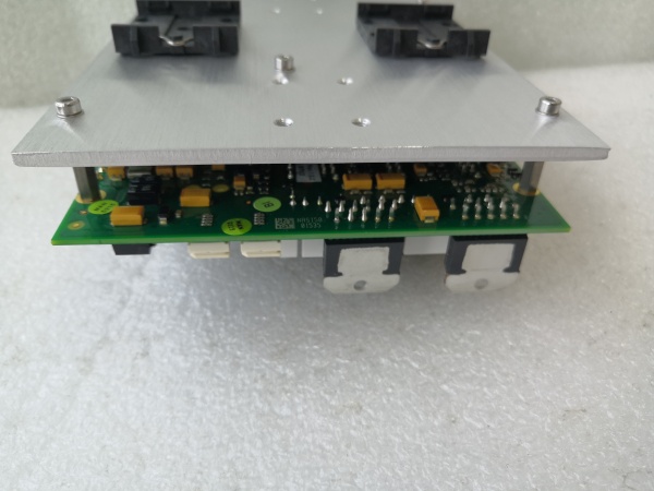
KONGSBERG RPC420 317114
Field Service Pitfalls: What Rookies Get Wrong
Channel-to-Channel Ground LoopsEach channel is isolated, but techs tie the analog commons together for “convenience” during wiring. This defeats isolation and creates ground loops when thruster drives have different ground references.
- Field Rule: Keep analog commons separate per channel. Measure resistance between channel commons—should be infinite (>1MΩ). If you need common references, use the bridge control system’s grounding scheme, not the RPC420’s.
Feedback Scaling MismatchThe thruster drive outputs 0-20mA, but the RPC420 expects 4-20mA. Techs configure the input for 4-20mA, then wonder why the unit reads zero at minimum thrust.
- Quick Fix: Verify feedback range with the drive documentation. Configure input scaling in the RPC420 parameters to match exactly—0-20mA or 4-20mA. Test with a signal simulator: apply 4mA, 12mA, 20mA and verify the display reads correctly. If you’re seeing 20% at zero speed, reconfigure the input.
Missing Watchdog ConfigurationThe RPC420 monitors communication health, but techs disable watchdog timers during commissioning and forget to re-enable them. When the bridge link fails, the thrusters hold their last command instead of failing to a safe state.
- Field Rule: Always enable watchdog with appropriate timeout (typically 100-500ms). Test it by disconnecting the bridge communication cable—the RPC420 should fault all channels to a safe state within the timeout period. Document this test—safety-critical systems require documented proof.
IP66 Seal DegradationThe enclosure is IP66 rated, but the cable glands loosen over time from vibration. Moisture enters through the gland threads, causing corrosion and intermittent faults.
- Field Rule: Check cable gland torque during quarterly maintenance. Re-seal with PTFE tape or thread compound if removed. If you see corrosion on connector pins, replace the entire unit—cleaning is a temporary fix in marine environments. IP66 only holds if the installation is maintained.


