
Description
Hard-Numbers: Technical Specifications
Analog I/O Configuration (RMP400-AA: Analog Version)
- Analog Inputs: Up to 24 channels
- 16 × current inputs (4-20 mA)
- 8 × voltage inputs (0-10 V)
- Individually configurable as current or voltage per channel
- Analog Outputs: 8 channels (individually configurable)
- Output range: 4-20 mA or 0-10 V
- Short-circuit proof loop current driver
- Resolution: 12-bit typical (dependent on configuration)
Digital I/O Configuration (RMP400-DD: Digital Version)
- I/O Channels: Up to 32 individually defined digital inputs or outputs
- Input Voltage: 24 VDC ±20% (19.2-28.8 VDC)
- Input Loop Current: Maximum 4 mA at 24 VDC loop voltage
- Channel “OFF” Current: <0.5 mA
- Channel “ON” Current: >3 mA
- Maximum Input Signal Frequency: 10 ms pulse
- Connectors: Screw terminals, 2.5 mm²
Communication Interfaces
- Dual Serial Process Bus (SPBus): RS-485 based, up to 2 MHz data rate
- Supports redundant configuration for fault tolerance
- 500V electrical isolation from control system
- Diagnostics: Loop-check and debugging from operator station and local data terminal
Power Supply
- Input Voltage: 24 VDC ±20% (19.2-28.8 VDC)
- Power Consumption: ~5 mA typical at 24 VDC (digital version)
- Protection: Reverse polarity, overvoltage protection
Safety and Diagnostics
- Safety Compliance: SIL 1 (Safety Integrity Level) compliant
- Fail-Safe: Watchdog activates fail-safe state upon loss of communication
- Diagnostics Features:
- Built-in self-test (BIST) for fault identification
- Earth Fault Detection (EFD)
- Line Fault Detection (LFD)
- Dual watchdogs for system monitoring
- Status Indication: LED indicators for normal operation and error condition
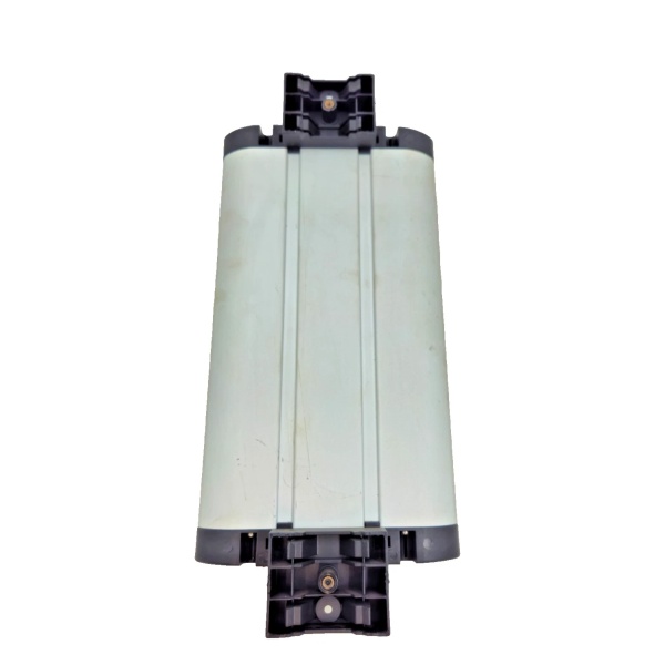
Mechanical Specifications
- Mounting: DIN standard rail-mounting with plug-in connections
- Dimensions (Approximate): 124 mm × 100 mm × 26 mm (W×H×D)
- Weight: ~1.135 kg (analog version)
- Operating Temperature: -40°C to +85°C (depending on revision and application)
- Protection Rating: IP20 typical (indoor cabinet mounting)

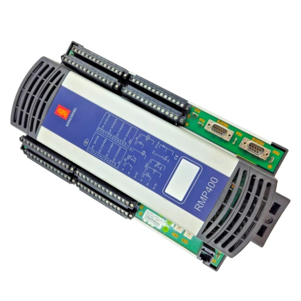
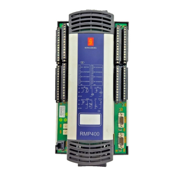
Kongsberg RMP400
The Real-World Problem It Solves
Running every sensor and actuator back to a central controller creates massive cable infrastructure—signal degradation over distance, installation complexity, and prohibitive cost. The RMP400 sits near field equipment, collecting local I/O signals and transmitting them to the controller via SPBus. This reduces wiring, simplifies installation, and improves noise immunity through local analog-to-digital conversion. With dual redundant SPBus interfaces and SIL 1 safety compliance, it ensures reliable operation in safety-critical applications where communication failures cannot be tolerated.
Where you’ll typically find it:
- Dynamic positioning (DP) systems with distributed I/O nodes across the vessel
- Fire and gas safety systems requiring SIL 1 compliance
- Process control cabinets in marine and offshore applications
- Remote I/O racks for valve position feedback and control
Bottom line: One RMP400 replaces dozens of long signal runs—reducing cable infrastructure, improving reliability through redundancy, and simplifying troubleshooting with built-in diagnostics.
Hardware Architecture & Under-the-Hood Logic
The RMP400 is a member of the Kongsberg RIO400 Remote Input/Output system. It acts as an interface between the Serial Process Bus (SPBus) and field devices—accepting analog or digital inputs from sensors and providing outputs to actuators. The unit communicates with a host controller (such as RCU500 or SBC500) via SPBus, forming a distributed I/O architecture.
-
Dual SPBus Communication Interface: The RMP400 features two independent SPBus interfaces supporting redundant operation. Each interface is electrically isolated (500V) from the control system to prevent ground loops and noise coupling. In redundant configuration, the unit continuously monitors both buses—if the primary bus fails, communication automatically switches to the secondary bus without interrupting system operation. SPBus operates at up to 2 MHz using RS-485 physical layer with Manchester encoding for noise immunity.
-
Analog Input Circuitry (RMP400-AA): Analog inputs support both 4-20 mA current loops and 0-10 V voltage signals. Each channel is individually configurable via software. The input circuitry includes:
- Current Loop Excitation: Short-circuit proof loop current driver supplies excitation for 2-wire transmitters.
- Input Filtering: Configurable low-pass filtering rejects high-frequency noise.
- Analog-to-Digital Conversion: Onboard ADC converts analog signals to digital values before transmission via SPBus, eliminating signal degradation over long cable runs.
-
Analog Output Circuitry: Analog outputs provide 4-20 mA or 0-10 V signals for control valves, variable speed drives, or other analog actuators. Each output channel is individually configurable and includes:
- Short-Circuit Protection: Outputs are protected against short circuits to ground or supply.
- Fail-Safe Behavior: Watchdog-driven fail-safe activates a predefined state upon communication loss—outputs can fail to a safe value (e.g., close valve) or hold last known value.
-
Digital Input/Output Circuitry (RMP400-DD): Digital inputs are opto-isolated and support 24 VDC signals with configurable debounce filtering. Digital outputs are transistor or relay outputs for driving loads such as solenoids,指示灯, or contactors. The channels can be configured individually as input or output, providing flexibility for mixed applications.
-
Diagnostics Subsystem: The RMP400 continuously monitors its health and reports faults to the host controller:
- Built-in Self-Test (BIST): Runs on startup and continuously checks for hardware faults.
- Earth Fault Detection (EFD): Monitors for ground faults on I/O wiring.
- Line Fault Detection (LFD): Detects open-circuit or short-circuit faults on analog or digital I/O lines.
- Dual Watchdogs: Hardware and software watchdogs monitor processor activity and communication integrity—if either watchdog expires, the unit enters fail-safe state.
-
Fail-Safe Operation: Upon loss of SPBus communication or watchdog timeout, the RMP400 activates fail-safe behavior:
- Digital outputs can be configured to go to a defined state (ON or OFF).
- Analog outputs can fail to a defined current or voltage value.
- Fail-safe activation is independent of communication loss type—bus fault, power loss, or controller failure all trigger the same predictable response.

Kongsberg RMP400
Field Service Pitfalls: What Rookies Get Wrong
Incorrect SPBus Termination and Biasing
The SPBus requires proper termination and biasing at both ends of the segment. Rookies forget to install termination resistors or install them incorrectly. Unterminated buses cause signal reflections, leading to communication errors, sporadic I/O failures, or complete communication loss. Worse, they might bias the bus incorrectly or not at all, causing marginal operation that fails in high EMI environments.
- Field Rule: Install 120Ω termination resistors on the first and last RMP400 units (or RCU500) on the SPBus segment. Verify termination by measuring resistance between the A-line and B-line at the open end—should be ~60Ω (two 120Ω resistors in parallel). For analog I/O units, check if the specific revision requires bus biasing resistors (typically 560Ω to 3.3V) for reliable operation in noisy environments.
Improper Analog Signal Shield Grounding
Analog inputs are susceptible to ground loops when field devices have different ground potentials. Techs connect the analog signal shield to ground at both the field device and the RMP400, creating a ground loop through the shield. This causes erratic readings, offset errors, or complete signal corruption—especially noticeable on 4-20 mA loops with long cable runs.
- Quick Fix: Terminate the analog signal shield at the RMP400 end only (single-point grounding). Leave the shield floating at the field device end or connect via a capacitor (1–10 nF) to block DC ground loops. For multi-conductor cables carrying multiple analog signals, ground all shields at the RMP400 end only. Verify shield isolation with a multimeter—resistance between shield and PE at the field device should be >1MΩ.
Ignoring Earth Fault Detection (EFD) Alarms
The RMP400’s Earth Fault Detection (EFD) monitors for ground faults on I/O wiring. New engineers silence EFD alarms without investigation, assuming they’re nuisance warnings. A ground fault indicates compromised insulation or wiring damage—left unaddressed, it causes intermittent operation, cross-talk between channels, or complete failure of the I/O circuit. In safety systems, EFD warnings must be taken seriously.
- Field Rule: When EFD alarm triggers, isolate the fault by disconnecting field devices one by one. Measure insulation resistance between each I/O line and ground—should be >1MΩ for 24VDC systems. Identify the compromised cable or device and replace it. For marine environments with high humidity, check for conduit moisture ingress and install desiccant if necessary. Never disable EFD monitoring—document and resolve all ground faults.
Incorrect Fail-Safe Configuration for Safety Systems
In safety applications, fail-safe behavior must be configured to drive the system to a safe state upon communication loss. Rookies leave fail-safe in default “hold last value” mode for safety-critical outputs like valve control signals. If the RMP400 loses communication, the valve holds its last position, potentially creating an unsafe condition. A properly configured system should fail to a defined safe state (e.g., close valve on loss of communication).
- Quick Fix: Review fail-safe configuration for all safety-related outputs during commissioning. For shutdown valves, configure fail-safe to drive to the safe position (fully open or fully closed depending on the process). For analog outputs, configure fail-safe to a defined value that puts the process in a safe state. Document the fail-safe behavior in system logic and verify by simulating communication loss (disconnect SPBus cable) and confirming outputs reach the expected safe state.
Forgetting to Verify Analog Output Calibration
Analog outputs drift over time due to component aging, temperature cycling, or power supply variations. Techs assume factory calibration remains accurate indefinitely, never verifying output accuracy during maintenance. Over months or years, a 4-20 mA output calibrated to 20 mA at 100% may drift to 19.5 mA, causing control valves to not fully open or process variables to deviate from setpoint.
- Field Rule: During quarterly maintenance, verify analog output accuracy using a calibrated loop calibrator. Command 0%, 25%, 50%, 75%, and 100% output and measure actual current or voltage. Acceptable tolerance is typically ±0.5% of full-scale (for 4-20 mA, ±0.08 mA). If drift exceeds tolerance, recalibrate the output per manufacturer procedure. Document calibration values and trend drift over time—accelerating drift indicates component degradation.
Overlooking Redundant SPBus Configuration
The RMP400 supports dual SPBus interfaces for redundancy, but rookies only wire one interface. If the single SPBus fails (cable cut, connector corrosion, bus fault), the unit loses all communication and I/O data becomes unavailable. In safety-critical or DP applications, this is unacceptable—the unit must maintain operation even with a single bus fault.
- Quick Fix: Wire both SPBus interfaces to separate bus segments powered from different sources. Verify that the unit detects faults on the primary bus and automatically switches to the secondary bus without operator intervention. Test by disconnecting the primary SPBus cable while monitoring I/O update rates—should remain within spec on the secondary bus. Document bus routing and redundancy testing in commissioning records.
Ignoring Watchdog Timeout Settings
The RMP400’s watchdog monitors communication integrity with the host controller. If communication is lost, the watchdog triggers fail-safe behavior. Rookies set watchdog timeout too short (e.g., 100 ms), causing nuisance fail-safe triggers during normal communication delays or bus contention. Alternatively, they set it too long (e.g., 5 seconds), causing excessive delay before fail-safe activation during an actual failure.
- Field Rule: Set watchdog timeout based on system communication cycle time. For SPBus systems with typical scan times of 50-200 ms, set watchdog to 3-5 times the scan time (e.g., 500-1000 ms). Verify that normal communication variations don’t trigger watchdog, but actual failures activate fail-safe within acceptable time. Test by simulating communication loss (disconnect SPBus) and measure time to fail-safe activation—should be within configured timeout but not excessively long.
Commercial Availability & Pricing Note
Please note: The listed price is for reference only and is not binding. Final pricing and terms are subject to negotiation based on current market conditions and availability.


