

Description
Hard-Numbers: Technical Specifications
The Real-World Problem It Solves
Distributed I/O systems are essential in modern process control—running every sensor and actuator back to a central controller creates massive cable costs, signal degradation over distance, and installation complexity. The RDIOR400 provides a compact remote I/O solution that sits near field equipment, collecting local I/O signals and transmitting them to the controller via SPBus. This reduces wiring, simplifies installation, and improves noise immunity through local analog-to-digital conversion.
Where you’ll typically find it:
- Distributed I/O racks in marine process control cabinets
- Offshore platform safety systems requiring local I/O concentration
- Dynamic positioning systems with remote I/O nodes
- Industrial process plants with distributed field devices
Bottom line: One RDIOR400 replaces dozens of long analog signal runs—reducing cable, improving reliability, and simplifying troubleshooting.
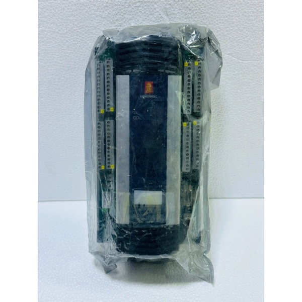
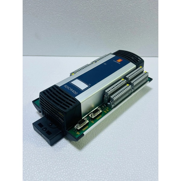
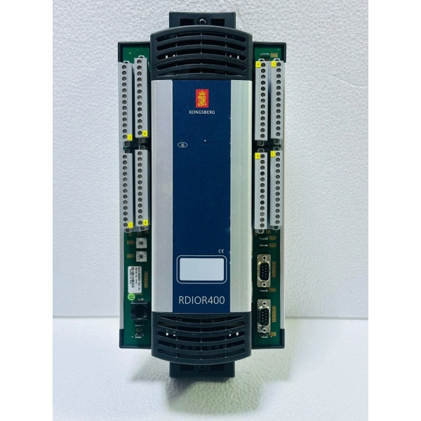
Kongsberg RDIOR400
Hardware Architecture & Under-the-Hood Logic
The RDIOR400 is a remote I/O unit that connects to field devices and communicates with a host controller (such as the RCU500) via SPBus. It provides a mix of digital and analog I/O channels in a compact DIN-rail mounted enclosure.
-
SPBus Communication Interface: The RDIOR400 communicates with the host controller via the Serial Process Bus (SPBus). Operating at up to 2 MHz with RS-485 physical layer and 500V isolation, SPBus provides noise immunity and long-distance capability. The unit supports daisy-chain configuration, allowing multiple RDIOR400 units on a single SPBus segment.
-
Digital I/O Channels: The unit provides multiple digital input and output channels for on/off field devices. Digital inputs are opto-isolated and support various voltage ranges (typically 24VDC). Digital outputs are relay or transistor outputs for driving loads like solenoids,指示灯, or contactors.
-
Analog I/O Channels: Analog inputs support various signal types including 0-10V, 4-20mA, thermocouple, and RTD inputs. Onboard analog-to-digital converters provide high-resolution measurement. Analog outputs provide 0-10V or 4-20mA signals for control valves, variable speed drives, or other analog devices.
-
Diagnostics and Status Indication: The unit features built-in diagnostics for channel faults, communication loss, and power supply monitoring. Status LEDs provide visual indication of unit health, SPBus communication status, and individual channel activity.
-
Power Supply: The RDIOR400 is powered from 24 VDC supply, typically daisy-chained between multiple units. The power input is protected against overvoltage and reverse polarity.
Kongsberg RDIOR400
Field Service Pitfalls: What Rookies Get Wrong
Incorrect SPBus Termination
The SPBus requires proper termination at both ends of the segment. Rookies forget to install termination resistors or install them incorrectly. Unterminated buses cause signal reflections, leading to communication errors, sporadic I/O failures, or complete communication loss. Worse, they might terminate every node instead of just the first and last.
- Field Rule: Install 120Ω termination resistors on the first and last RDIOR400 units on the SPBus segment. Verify termination by measuring resistance between the A-line and B-line at the open end—should be ~60Ω (two 120Ω resistors in parallel). Never terminate intermediate nodes.
Ground Loop Issues with Analog Inputs
Analog inputs are susceptible to ground loops when field devices have different ground potentials. Techs connect the analog signal shield to ground at both the field device and the RDIOR400, creating a ground loop through the shield. This causes erratic readings, offset errors, or complete signal corruption.
- Quick Fix: Terminate the analog signal shield at the RDIOR400 end only (single-point grounding). Leave the shield floating at the field device end or connect via a capacitor (1–10 nF) to block DC ground loops. For high-noise environments, use differential analog inputs and twisted-pair shielded cable with the shield grounded at one end only.
Ignoring Input Filtering and Signal Conditioning
The RDIOR400 provides configurable input filtering and signal conditioning parameters. Rookies leave default settings without considering field signal characteristics. Fast-switching digital inputs may cause bounce, creating false counts. Slow analog signals with inadequate filtering cause jittery readings.
- Field Rule: Configure input filtering according to signal type. For mechanical switches, use debounce filtering (typically 10-50ms). For analog inputs, configure appropriate filtering time constants to balance response time and noise rejection. Test with actual field signals during commissioning to verify settings.
Overloading Power Supply on Daisy-Chained Units
Multiple RDIOR400 units are often powered from a single 24 VDC supply via daisy-chained wiring. New engineers fail to calculate total power consumption, overloading the supply. Voltage drops across the chain cause the last unit to operate below spec, leading to erratic behavior or complete failure.
- Field Rule: Calculate total power consumption per unit and sum across all units in the chain. Ensure the 24 VDC supply has adequate margin (typically 20-30%). Measure voltage at the last unit under full load—should be within spec (typically 24VDC ±10%). If voltage drop is excessive, increase wire gauge or use multiple power feed points.
Commercial Availability & Pricing Note
Please note: The listed price is for reference only and is not binding. Final pricing and terms are subject to negotiation based current market conditions and availability.


