
Description
Hard-Numbers: Technical Specifications
- Processor: DSP-based motion controller (32-bit floating point)
- Gate Drive Type: 3-phase IGBT bridge driver with dead-time control
- Switching Frequency: 4 kHz / 8 kHz / 16 kHz (configurable)
- Current Sensing: Hall-effect sensors (2mV/A sensitivity)
- DC Bus Voltage Rating: 560VDC maximum
- Analog Inputs: 2 × ±10V, 16-bit resolution
- Digital I/O: 8 opto-isolated inputs, 4 transistor outputs
- Feedback Interfaces: Encoder (A/B/Z), Resolver, Hiperface, EnDat
- Isolation Rating: 500V optical (logic to power stage)
- Operating Temperature: 0°C to +70°C (board level)
- Memory: 128KB Flash, 32KB RAM (parameter storage)
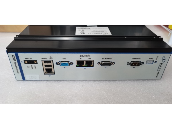
- Communication: RS-232/485, optional fieldbus via daughter card
- Dimensions: 180mm × 150mm × 30mm (PCB footprint)

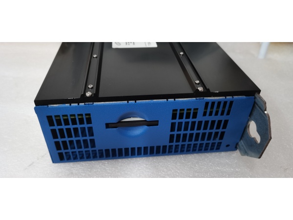
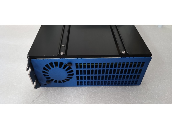
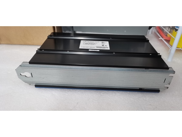
Kollmorgen T126-0001 REV.P3
The Real-World Problem It Solves
Your S700 drive won’t power up, runs erratically, or faults on IGBT errors—often this board is the culprit. The T126-0001 handles everything from motion control loops to IGBT gate driving, and when it fails, replacing it means either buying a whole new drive or tracking down the exact board revision. Having this board identified lets you repair at board level instead of scrapping a $5,000 drive.
Where you’ll typically find it:
- Main control board inside S700/S600 series servo drives
- Power stage interface between logic and IGBT modules
- Central hub for all drive signaling and feedback processing
The bottom line: It’s the brain and nervous system of the S700 drive—replacing this board resurrects dead drives without requiring complete system replacement, saving thousands in downtime and equipment costs.
Hardware Architecture & Under-the-Hood Logic
This board sits at the heart of the servo drive, connecting the user interface/parameter system to the power stage and motor. The DSP executes motion control loops while dedicated gate driver circuitry switches the IGBTs. Multiple feedback interfaces support various encoder and resolver types.
Signal flow breaks down like this:
- User commands enter via analog, digital, or fieldbus interfaces
- DSP processes command and feedback signals in real-time (10-100 kHz loop rates)
- Current feedback from Hall sensors and feedback device data feed into control algorithms
- PWM generator creates IGBT gate drive signals with dead-time protection
- Gate driver circuitry level-shifts and amplifies PWM for IGBT control
- IGBT switching produces 3-phase AC output to motor
- Protection circuits monitor overcurrent, overtemperature, and ground faults
- Status information drives front-panel display and LED indicators
Kollmorgen T126-0001 REV.P3
Field Service Pitfalls: What Rookies Get Wrong
Ignoring Revision CompatibilityTechs pull a board from an older S700 drive and drop it into a newer one—or vice versa. Parameter files don’t load correctly, or the drive faults immediately because the firmware expects different hardware.
- Field Rule: Match the revision exactly (REV.P3 in this case). Check the drive nameplate against the board revision label. Firmware versions are tied to hardware revisions—mismatching them creates unpredictable behavior. Keep a revision log for your fleet.
Gate Driver Damage from Improper Power-UpApplying control power before DC bus precharge completes blows the gate driver ICs. The high-side IGBTs turn on into the uncharged bus and short-circuit.
- Quick Fix: Verify the precharge cycle completes before enabling the control board. Watch the DC bus LED—it should ramp to nominal voltage (560VDC) before the control board powers up. If gate drivers are already blown, the board is scrap—don’t waste time troubleshooting further.
Missing Parameter BackupTechs swap boards without backing up parameters, then discover the default parameters don’t match the application. The motor runs poorly or faults during commissioning.
- Field Rule: Always extract parameter files before board removal. Use the drive’s RS-232 interface or fieldbus connection to download the parameter set. Store backups by drive serial number—this saves hours during commissioning and provides a baseline for future troubleshooting.


