
Description
Hard-Numbers: Technical Specifications
- Continuous Output Current: 20A rms (3-phase sinusoidal current)
- Peak Output Current: 60A rms (for 10 ms)
- Input Voltage: 200–240VAC 3-phase (230V nominal); accepts ±10% variation
- Input Frequency: 50/60Hz
- Command Input: ±10V analog input for speed, position, or torque command
- Feedback Interfaces: Incremental encoder (TTL, HTL), resolver
- Control Modes: Position, velocity, torque (analog commanded)
- Current Loop Bandwidth: >500 Hz typical (vector mode)
- Position Loop Bandwidth: >100 Hz typical
- Encoder Resolution: Up to 16,384 counts/rev (incremental), higher for resolver
- Integrated Safety: No integrated STO (external relay recommended for safety 终止)
- Positioning Accuracy: ±1 encoder count typical
- Operating Temperature: 0°C to +50°C ambient (de-rate above 40°C)
- Storage Temperature: -25°C to +85°C
- Humidity: 10–90% RH non-condensing
- Power Consumption: ~2–3 kW at full load (varies with motor size)
- Certifications: CE, UL, CSA (varies by drive certification)
- Dimensions: 300 mm × 120 mm × 200 mm (11.8″ × 4.7″ × 7.9″) with mounting brackets
- Mounting: DIN rail or panel mount
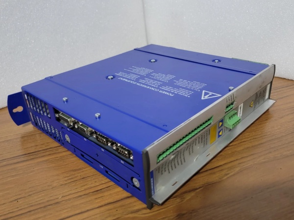
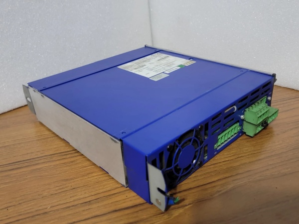
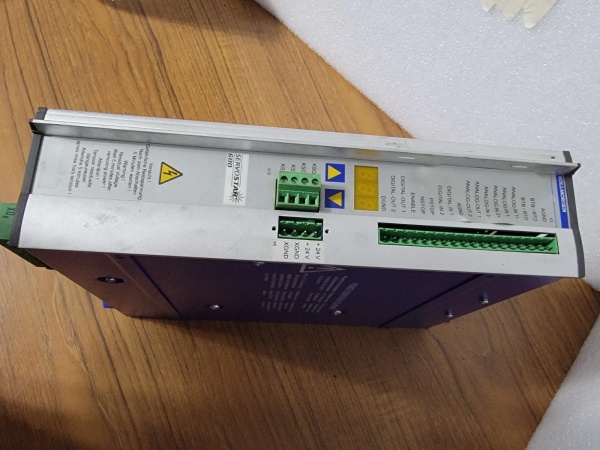
Kollmorgen SERVOSTAR 610-AS
The Real-World Problem It Solves
Many high-power servo applications (heavy material handling, large packaging lines, forming machinery) use legacy analog command systems that can’t easily be upgraded to digital control. These systems need high continuous current (20A+) for large torque loads, but low-power drives (like the SERVOSTAR 610-AS) can’t handle the current. The SERVOSTAR 614-AS delivers 20A continuous current with 60A peak, supporting high-torque servo motors while maintaining analog ±10V command compatibility. This eliminates the need for expensive control system retrofits while enabling high-power motion control.
Where you’ll typically find it:
- Heavy-duty material handling with high-torque requirements
- Large packaging lines and palletizers requiring high dynamic performance
- Legacy retrofit applications with existing analog command systems
- Presses and forming machinery with high inertia loads
Bottom line: The SERVOSTAR 614-AS provides high-current analog servo capability—big power without throwing out your legacy control system.
Hardware Architecture & Under-the-Hood Logic
The SERVOSTAR 614-AS is a high-current variant of the SERVOSTAR 610-AS, designed for applications requiring higher continuous current output. It accepts ±10V analog command and performs closed-loop servo control for position, velocity, or torque mode. The architecture is similar to the 610-AS but scaled for 20A operation.
-
Analog Input Stage: The ±10V command signal is conditioned via low-pass filters to reject noise and offset errors. The input range is ±10V, with user-configurable scaling supported via front-panel software or DIP switches. An input monitor circuit detects open-circuit or short-circuit faults on the command line.
-
Power Input Stage: The 3-phase input goes through EMI filtering, a bridge rectifier, and bulk capacitors to generate ~320VDC DC bus voltage. Higher capacitance compared to the 610-AS to handle 20A continuous current ripple. The DC bus voltage is monitored continuously for overvoltage and undervoltage.
-
Motor Drive Stage: The DC bus is converted to 3-phase PWM output using IGBTs rated for 230VAC and 20A continuous current. The PWM frequency is ~8 kHz (fixed), generating a near-sinusoidal current waveform. Current sensors in each phase monitor output current for vector control and overcurrent protection. The IGBTs are heatsinked more aggressively to handle higher current.
-
Digital Servo Control Logic: The analog command signal is converted to digital via a 12-bit ADC. A DSP processor closes the current, velocity, and position loops based on the digital value. Control mode (position, velocity, torque) is selected via DIP switch or configuration software. Loop gains are factory-tuned for high-current applications but can be adjusted for specific loads.
-
Feedback Interface: The drive supports incremental encoders (TTL or HTL) and resolvers as feedback. The encoder signal is processed to provide velocity and position feedback for closed-loop control. In resolver mode, the resolver position is decoded using an internal resolver-to-digital converter (RDC).
-
Dynamic Braking: The SERVOSTAR 614-AS requires an external braking resistor for high-current applications. The drive has terminals for connecting an external braking resistor to dissipate regenerative energy during deceleration. The resistor power rating must be sized based on the kinetic energy of the load—Kollmorgen provides sizing tools for this calculation.
Kollmorgen SERVOSTAR 610-AS
Field Service Pitfalls: What Rookies Get Wrong
Using Undersized Braking Resistors
At 20A continuous current, regenerative energy during deceleration is significantly higher than in 10A drives. Rookies install a standard 100W braking resistor designed for the 610-AS on a 614-AS system. The resistor overheats, may catch fire, or fails open-circuit—causing DC bus overvoltage fault and uncontrolled motor coasting.
- Field Rule: Calculate regenerative braking power required for the worst-case deceleration using Kollmorgen’s sizing tool. The 614-AS typically requires a 200W–500W external braking resistor depending on load inertia and deceleration rate. Install the resistor with adequate ventilation and thermal protection. Monitor resistor temperature during initial commissioning.
Ignoring Heatsink Clearance for High-Current Operation
The SERVOSTAR 614-AS dissipates significantly more heat than the 610-AS at full load. Techs mount the drive flush against the cabinet backplate or adjacent equipment without airflow clearance. The heatsink can’t dissipate heat effectively, internal temperatures rise above 60°C, and the drive goes into thermal derating or fault mode.
- Quick Fix: Maintain minimum 150mm clearance above and below the drive’s heatsink area for convection cooling. For ambient temperatures above 40°C, install forced air cooling (120mm fan) directed at the heatsink. Monitor internal drive temperature via front-panel diagnostics. If temperature exceeds 60°C, reduce load current or improve cooling.
Overloading the Drive with Inertia Ratios >10
High-current drives are often used with large inertia loads (e.g., heavy gantry, press brakes). Inertia ratio >10 causes unstable velocity control and position error. New engineers crank up velocity loop gains to compensate, but this causes current oscillation and overheating.
- Field Rule: Calculate inertia ratio before tuning the drive. If inertia ratio >10, reduce velocity loop gains and use position feedforward to improve responsiveness. Consider adding a gearbox to reduce inertia ratio to <5 if precise positioning is required. Tune current, velocity, and position loops sequentially—current first, then velocity, then position.
Running the Drive at Maximum Current in Hot Ambient
The 614-AS is rated for 20A continuous current at up to 40°C ambient. Above 40°C, the drive de-rates output current automatically (~5% per °C). Rookies assume the drive can deliver 20A continuous in a 50°C cabinet. The drive de-rates to 15A or less, causing motor stall or position error alarms.
- Quick Fix: Measure ambient temperature in the cabinet during peak operation. If ambient exceeds 40°C, de-rate the load accordingly: for 45°C, assume 17.5A maximum continuous; for 50°C, assume 15A maximum. Improve cabinet ventilation or relocate the drive to a cooler area if full current is required.
Forgetting to Ground the Motor Frame Properly
At 20A output current, motor frame grounding becomes critical for EMI control and safety. Techs connect the motor’s protective earth (PE) to the drive’s ground terminal with a thin 16AWG wire. High current flow causes voltage drops, EMI issues, and potential safety hazards.
- Field Rule: Use a minimum 6 mm² (10 AWG) grounding cable from the motor frame to the drive’s PE terminal and to the equipment’s safety ground bus. Verify resistance between motor frame and drive PE is <1Ω using a low-resistance ohmmeter. Never rely on the motor cable’s ground wire alone—use a separate ground strap for high-current applications.
Commercial Availability & Pricing Note
Please note: The listed price is for reference only and is not binding. Final pricing and terms are subject to negotiation based on current market conditions and availability.


