
Description
Hard-Numbers: Technical Specifications
- Continuous Output Current: 10A rms (3-phase sinusoidal current)
- Peak Output Current: 30A rms (for 10 ms)
- Input Voltage: 200–240VAC 3-phase (230V nominal); accepts ±10% variation
- Input Frequency: 50/60Hz
- Command Input: ±10V analog input for speed, position, or torque command
- Feedback Interfaces: Incremental encoder (TTL, HTL), resolver
- Control Modes: Position, velocity, torque (analog commanded)
- Current Loop Bandwidth: >500 Hz typical (vector mode)
- Position Loop Bandwidth: >100 Hz typical
- Encoder Resolution: Up to 16,384 counts/rev (incremental), higher for resolver
- Integrated Safety: No integrated STO (external relay recommended for safety 终止)
- Positioning Accuracy: ±1 encoder count typical
- Operating Temperature: 0°C to +50°C ambient (de-rate above 40°C)
- Storage Temperature: -25°C to +85°C
- Humidity: 10–90% RH non-condensing
- Power Consumption: ~1–2 kW at full load (varies with motor size)
- Certifications: CE, UL, CSA (varies by drive certification)
- Dimensions: 240 mm × 120 mm × 180 mm (9.4″ × 4.7″ × 7.1″) with mounting brackets
- Mounting: DIN rail or panel mount
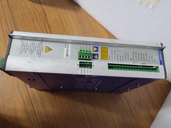
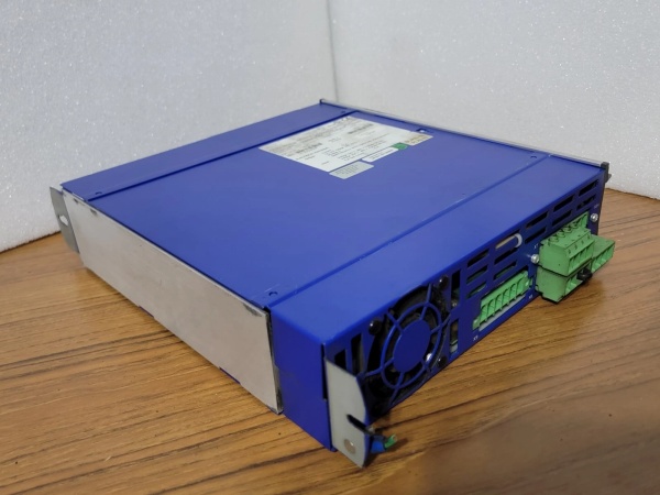
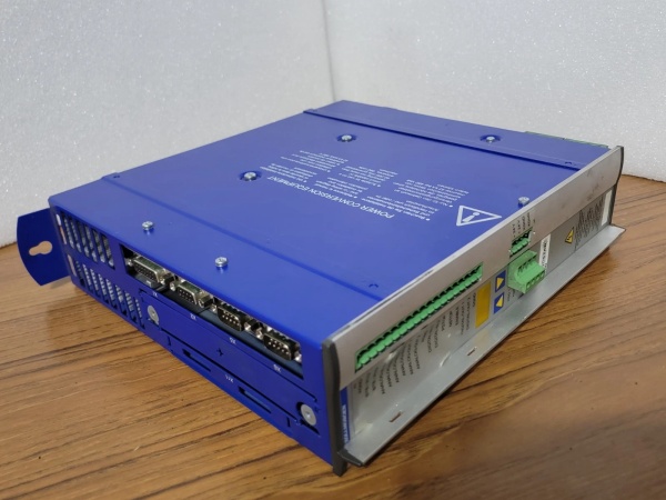
Kollmorgen SERVOSTAR 610-AS
The Real-World Problem It Solves
Many legacy industrial machines and control systems use analog ±10V command signals to drive servo motors. Migrating to modern digital drives requires expensive and time-consuming retrofits to upgrade the control system. The SERVOSTAR 610-AS accepts analog ±10V input and performs closed-loop servo control, maintaining compatibility with existing legacy command systems while delivering precise motion control. It eliminates the need to replace the entire control system just to upgrade servo performance.
Where you’ll typically find it:
- Retrofit applications with legacy analog command systems
- Simple positioning and velocity control applications
- Standalone motion systems with direct operator input via potentiometer
- Low-cost, high-performance analog servo systems
Bottom line: The SERVOSTAR 610-AS bridges legacy and modern—analog command compatibility with digital closed-loop precision.
Hardware Architecture & Under-the-Hood Logic
The SERVOSTAR 610-AS is a single-axis analog servo amplifier designed for high-performance motion control with analog command input. It accepts ±10V analog command and performs closed-loop servo control for position, velocity, or torque mode. Its architecture combines analog signal processing with digital servo loop closure for high accuracy.
-
Analog Input Stage: The ±10V command signal is conditioned via low-pass filters to reject noise and offset errors. The input range is ±10V, but the drive also supports user-configurable scaling (e.g., ±5V command for reduced range). An input monitor circuit detects open-circuit or short-circuit faults on the command line.
-
Power Input Stage: The 3-phase input goes through EMI filtering, a bridge rectifier, and bulk capacitors to generate ~320VDC DC bus voltage. The DC bus voltage is monitored continuously—if it drops below threshold, the drive faults. Overvoltage protection clamps peak voltage during regenerative braking.
-
Motor Drive Stage: The DC bus is converted to 3-phase PWM output using IGBTs rated for 230VAC. The PWM frequency is ~8 kHz (fixed), generating a near-sinusoidal current waveform. Current sensors in each phase monitor output current for vector control and overcurrent protection.
-
Digital Servo Control Logic: The analog command signal is converted to digital via a 12-bit ADC. A DSP processor closes the current, velocity, and position loops based on the digital value. Control mode (position, velocity, torque) is selected via DIP switch or configuration software.
-
Feedback Interface: The drive supports incremental encoders (TTL or HTL) and resolvers as feedback. The encoder signal is processed to provide velocity and position feedback for closed-loop control. In resolver mode, the resolver position is decoded using an internal resolver-to-digital converter (RDC).
-
Dynamic Braking: An optional internal braking resistor dissipates regenerative energy during deceleration. If no resistor is installed, the drive faults on DC bus overvoltage during rapid deceleration. External braking resistors can be connected via the drive terminals for higher braking requirements.
Kollmorgen SERVOSTAR 610-AS
Field Service Pitfalls: What Rookies Get Wrong
Misinterpreting ±10V Command Scaling
The SERVOSTAR 610-AS accepts ±10V command, but the scaling of voltage to output depends on the motor. A 1000 rpm motor may use ±10V = ±1000 rpm, while a 5000 rpm motor may use ±10V = ±5000 rpm. Rookies assume all motors scale ±10V to the maximum speed, leading to incorrect speed output and potential motor damage.
- Field Rule: Configure command scaling based on motor parameters using the drive’s front-panel configuration software or DIP switches. Verify that ±10V input yields the expected speed or position range during commissioning. Test with a calibrated voltage source to confirm output matches commanded value.
Overlooking Resolver Phase Alignment
When using a resolver as feedback, resolver phase alignment is critical. Rookies connect resolver wires without phasing them correctly. The drive can’t resolve position accurately, leading to unstable velocity control or position error. The motor may oscillate or not respond to commands properly.
- Quick Fix: Align resolver phases following Kollmorgen’s procedure. Typically, this involves manually rotating the motor shaft to a known position (e.g., phase A aligned with pole), then adjusting resolver offsets in the drive. Use an oscilloscope to verify resolver sine/cosine waveforms are in phase with position.
Using Unshielded Command and Encoder Cables
The SERVOSTAR 610-AS is sensitive to EMI, especially analog input and encoder signals. Techs use unshielded cables for command and encoder wiring. EMI-induced voltage noise corrupts the analog command or encoder feedback, causing erratic motion, position error, or drive faults.
- Field Rule: Use shielded twisted-pair cables for analog command and encoder wiring. Terminate the shield at the drive end only to avoid ground loops. Separate signal cables from power cables to minimize crosstalk. If significant EMI is present (e.g., near VFDs or motors), use double-shielded cables with grounded outer shields.
Neglecting Current Loop Tuning for Torque Control
In torque control mode, current loop tuning is critical for accuracy and stability. New engineers leave current loop gains at default settings. If gains are too low, torque control is sluggish; if too high, the current loop oscillates, leading to noisy motor current and increased heat.
- Field Rule: Tune the current loop during commissioning. Use a current clamp to measure motor current and verify it follows commanded torque (via analog input). Adjust current loop gains for minimal overshoot and fast response. Monitor motor temperature during tuning to avoid overheating.
Overheating the Drive with Inadequate Cooling
The SERVOSTAR 610-AS dissipates significant heat at full load (10A continuous). Rookies mount the drive in a non-ventilated enclosure or without proper clearance. Internal temperatures exceed 50°C, causing thermal overload fault or premature component failure.
- Quick Fix: Maintain minimum 100mm clearance around the drive for convection cooling. If ambient temperature exceeds 40°C, add forced air cooling directed at the drive’s heatsink. Monitor internal drive temperature via front-panel diagnostics. If temperature exceeds 50°C, reduce load current by ~10% per °C above limit.
Commercial Availability & Pricing Note
Please note: The listed price is for reference only and is not binding. Final pricing and terms are subject to negotiation based on current market conditions and availability.


