
Description
Hard-Numbers: Technical Specifications
- Continuous Output Current: 20A rms (3-phase sinusoidal current)
- Peak Output Current: 60A rms (for 10 ms)
- Input Voltage: 200–240VAC 3-phase (230VAC nominal); accepts ±10% variation
- Input Frequency: 50/60Hz
- Max Output Voltage: ~85% of input line voltage (vector mode)
- Supported Motor Types: Kollmorgen AKM series servo motors (400V and 230V)
- Feedback Interfaces:
- Absolute and incremental encoders (Heidenhain, Siemens, Fanuc protocols)
- Resolvers, SinCos encoders, BiSS interface
- Control Modes: Position, velocity, torque, camming, gearbox emulation
- Current Loop Bandwidth: >1 kHz typical (vector mode)
- Position Loop Bandwidth: >200 Hz typical
- Integrated Safety: STO (Safe Torque Off) per IEC 61508 (SIL 3)
- Encoder Resolution: Up to 16,384 counts/rev (incremental), higher for absolute
- Operating Temperature: 0°C to +50°C ambient (de-rate above 40°C)
- Storage Temperature: -25°C to +85°C
- Humidity: 10–90% RH non-condensing
- Power Consumption: ~2–3 kW at full load (varies with motor size)
- Certifications: CE, UL, CSA, IEC 61800-5-1 (EMC), IEC 61508 (STO)
- Dimensions: 360 mm × 150 mm × 200 mm (14.2″ × 5.9″ × 7.9″) with mounting brackets
- Mounting: DIN rail or panel mount
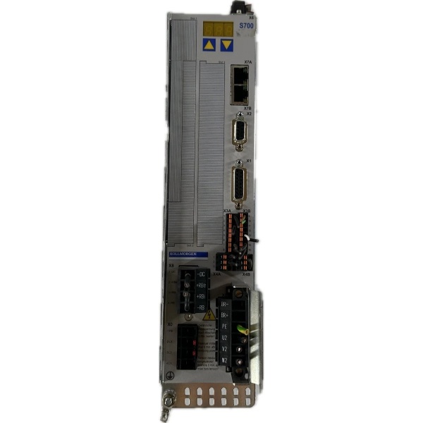
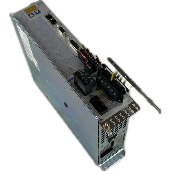
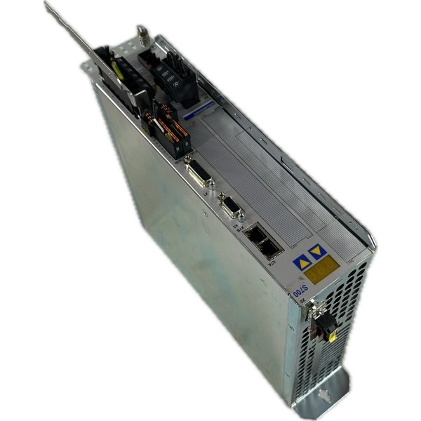
Kollmorgen S71201-NA
The Real-World Problem It Solves
High-torque industrial applications (e.g., press brakes, injection molding machines, large material handling equipment) need servo drives that can deliver continuous high current without overheating or losing precision. Traditional analog servo drives or low-power digital drives can’t handle the current requirements for heavy loads or generate sufficient torque for slow-speed, high-torque applications. The S71201-NA delivers continuous 20A rms current with peak current up to 60A, making it suitable for large Kollmorgen AKM servo motors up to ~20 kW power rating. Its digital vector control ensures tight current regulation, low-speed torque control, and dynamic performance for demanding motion profiles.
Where you’ll typically find it:
- Large material handling equipment (crane positioning, gantry motion)
- Injection molding machines for precise valve gate control
- Heavy-duty press brakes with axis synchronization requirements
- Industrial robots with payloads >50 kg requiring high dynamic performance
Bottom line: The S71201-NA is the muscle for heavy-duty motion control—high continuous current, precise torque regulation, and integrated safety functions in a compact form factor.
Hardware Architecture & Under-the-Hood Logic
The S71201-NA is a digital servo amplifier designed for single-axis motion control in the Kollmorgen S700 series. It accepts 230VAC 3-phase input, generates a sinusoidal PWM output for the servo motor, and integrates with encoder feedback to close the current, velocity, and position loops. Inside, it features three main sections: power input, motor drive, and control logic.
-
Power Input Stage: The 3-phase input goes through EMI filtering, a bridge rectifier, and bulk capacitors to generate a smooth DC bus voltage (~320VDC from 230VAC). The DC bus voltage is monitored continuously—if it drops below threshold (e.g., due to input undervoltage), the drive goes into fault mode to protect the motor and drive. Overvoltage protection clamps the DC bus to limit peak voltages during dynamic braking or regenerative operation.
-
Motor Drive Stage: The DC bus voltage is converted to 3-phase PWM output using insulated-gate bipolar transistors (IGBTs). The IGBTs switch at ~8 kHz (variable) to create a sinusoidal output current. A current sensor in each phase monitors output current for vector control and overcurrent protection. Vector control uses space vector PWM (SVPWM) to deliver optimized current waveform to the motor, minimizing torque ripple even at low speeds.
-
Digital Control Logic: A 32-bit DSP processor handles real-time servo loops:
- Current Loop: Faster than 1 kHz loop closure for precise current regulation and low ripple torque. The current sensor feedback is processed, and error compared to current reference generates PWM duty cycle.
- Velocity Loop: ~100–200 Hz loop closure uses encoder feedback to regulate motor speed, compensating for load changes or speed disturbances.
- Position Loop: ~50–100 Hz loop closure uses encoder feedback to regulate position, ensuring the motor follows commanded profiles accurately.
- Safety Logic: Hardware-implemented STO (Safe Torque Off) per IEC 61508 SIL 3. If an emergency 终止 is triggered or STO is activated, the drive immediately disconnects power to the motor stator by switching off all IGBTs.
-
Feedback Interface: The drive supports multiple feedback types: incremental encoders, resolvers, absolute encoders (BiSS, SSI protocols), and Heidenhain protocols. The feedback interface processes encoder signals to provide velocity and position feedback for closed-loop control. For absolute encoders, position is available at power-up without homing.
-
Dynamic Braking Regeneration: When the motor operates in regenerative mode (coasting or decelerating), kinetic energy is converted back into electrical energy, charging the DC bus. If the DC bus voltage exceeds the regenerative braking threshold, the drive uses a braking resistor (external or internal option) to dissipate excess energy, preventing overvoltage and bus fault.
-
Front-Panel Interface: The drive features a backlit LCD panel and keypad for parameter configuration, fault monitoring, and diagnostic data. Parameters include motor type, feedback type, control mode, loop gains, and dynamic braking configuration. The panel displays current status words, actual values (position, velocity, torque), and fault codes with descriptions.
Kollmorgen S71201-NA
Field Service Pitfalls: What Rookies Get Wrong
Mismatching Motor and Drive Voltage Ratings
I’ve seen techs install a 400V AKM motor on an S71201-NA (230VAC input) drive because they think “it will work with lower voltage.” The drive can only output ~85% of input line voltage—~200VAC phase-to-phase for a 230V input. This is insufficient for a 400V motor, which typically needs >320VAC phase-to-phase at full speed. The motor underperforms, struggles to accelerate, or trips the drive on “current limit exceeded” due to insufficient voltage.
- Field Rule: Match motor voltage rating to drive input voltage. Use S71201-NA (230VAC input) for 230V AKM motors, and a 400V drive (S71401-NA) for 400V AKM motors. Verify motor data sheet phase voltage before connecting—never underdrive a 400V motor on a 230V drive.
Ignoring Cooling Requirements at High Ambient Temperatures
The S71201-NA dissipates significant power under full load. Rookies mount the drive in a non-ventilated cabinet or without clearance around the cooling fins. When ambient temperature exceeds 40°C, the drive de-rates output current automatically (typically ~5% per °C above 40°C) to prevent overtemperature fault. The drive can’t deliver rated current, leading to motor stall or position error.
- Quick Fix: Maintain minimum 100mm clearance around drive cooling fins for convection cooling. For ambient temperatures above 40°C, install forced air cooling (120mm fan) directed at the drive’s cooling fin area. Monitor internal drive temperature via the keypad or drive diagnostics. If temperature exceeds 60°C, increase airflow or de-rate the load to prevent fault.
Setting Loop Gains Too High for Heavy Inertia Loads
In applications with large load inertia (e.g., press brakes, heavy gantry), high loop gains cause oscillations and position overshoot. New engineers crank up position loop gain to maximize responsiveness, not realizing heavy inertia damping requires lower gain settings. The result: position instability, jittery motion, or position error alarms.
- Field Rule: Calculate inertia ratio (load inertia to motor inertia) before setting gains. If inertia ratio >10, reduce loop gains and use position feedforward instead to improve responsiveness. Tune current, velocity, and position loops sequentially—current loop first, then velocity loop, then position loop. Use the drive’s auto-tune feature to calculate initial gain settings, then fine-tune manually based on actual performance.
Failing to Ground the Drive Properly
The S71201-NA requires proper PE (protective earth) grounding to prevent EMI/RFI issues, ensure operator safety, and protect the drive’s internal components. Rookies use undersized grounding cables or connect the drive chassis to signal ground instead of safety ground. Poor grounding leads to excessive motor current ripple, reduced performance, and potential safety hazards.
- Field Rule: Use a grounding cable with cross-section at least 6 mm² (10 AWG) for the main ground connection. Connect the drive’s PE terminal to the equipment’s safety ground bus, not signal ground. Use separate grounding cables for motor and encoder to avoid ground loops. Verify resistance between drive chassis and safety ground is <1Ω using a low-resistance ohmmeter.
Neglecting Regenerative Braking Configuration
In applications with rapid deceleration, the motor operates in regenerative mode, returning energy to the DC bus. If a braking resistor isn’t installed or sized properly, DC bus voltage spikes, triggering an overvoltage fault (F023). Rookies think the drive has a fault but don’t realize it’s just an overvoltage due to rapid deceleration without regeneration.
- Quick Fix: Calculate regenerative braking power required for rapid deceleration. Use the drive’s dynamic braking resistor sizing tool in S700 software. Install an external braking resistor with minimum resistance and maximum power rating based on calculation. Configure regenerative braking parameters in the drive to enable braking resistor usage during deceleration.
Overlooking STO Input Wiring
The S71201-NA has integrated STO (Safe Torque Off) functionality. New engineers wire the STO input incorrectly (e.g., closed circuit during normal operation) or omit STO wiring entirely. If STO is activated (circuit open), the drive shuts off torque output immediately—critical for emergency 终止. Incorrect wiring may trigger unintended STO activation or prevent it from activating when needed.
- Field Rule: Wire STO inputs per IEC 61508 recommendations: normally-closed input, open circuit triggers STO. Verify STO functionality during commissioning—open the STO input and check that motor 终止s with no torque output within 10 ms. Confirm that the STO LED illuminates on the drive front panel. Document STO wiring in safety procedures.
Commercial Availability & Pricing Note
Please note: The listed price is for reference only and is not binding. Final pricing and terms are subject to negotiation based on current market conditions and availability.


