
Description
Hard-Numbers: Technical Specifications
- Protocol: Profibus-DP per EN 50170, IEC 61158
- Data Rate: 9.6 kbps to 12 Mbps (selectable via DIP switches)
- Interface Type: RS-485 half-duplex (2-wire bus)
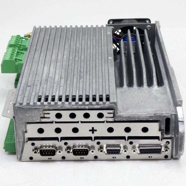
- Connector: 9-pin D-Sub male (DB9) per Profibus specification
- Profibus Profile: PROFIdrive Profile (PROFIdrive V3/V4)
- Node Address: 0–126 (set via rotary switches or DIP)
- Bus Termination: 150Ω internal termination (switchable)
- Isolation: 500VDC galvanic isolation between bus and drive internal logic
- Response Time: <1 ms cyclic data exchange (at 12 Mbps)
- Cyclic Data Length: Up to 64 bytes input + 64 bytes output
- Diagnostic Support: Extended diagnostics per IEC 61158-6
- Operating Temperature: 0°C to +50°C ambient
- Storage Temperature: -25°C to +85°C
- Humidity: 10–90% RH non-condensing
- Power Consumption: ~1W (powered from Servostar 300 drive backplane)
- Certifications: CE, UL, TÜV (varies by drive certification)
- Dimensions: Module plugs into Servostar 300 option slot; extends ~50mm beyond drive enclosure
- Mounting: Pluggable option card in Servostar 300 drive
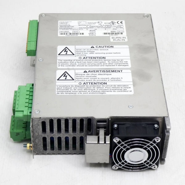
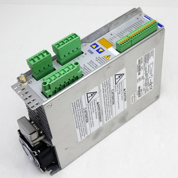
KOLLMORGEN S30301-PB
The Real-World Problem It Solves
Servo drives in automated machinery need real-time command and feedback data from the motion controller or PLC. Using analog command signals (±10V) or discrete I/O for each drive limits data bandwidth and accuracy, and wiring becomes a nightmare with multiple axes. The S30301-PB integrates the Servostar 300 servo drive directly into a Profibus-DP network, enabling high-speed communication (up to 12 Mbps) for position, velocity, torque commands, and comprehensive diagnostic data—all over a single twisted-pair cable. The drive becomes a network node, reducing wiring complexity and enabling synchronized motion control across multiple axes.
Where you’ll typically find it:
- Packaging machinery with multiple servo axes requiring synchronized motion
- Printing presses and converting equipment with tight registration requirements
- Robotic systems and material handling where precise servo control and diagnostics are needed
Bottom line: It turns a standalone servo drive into a networked motion node—cleaner wiring, higher precision, and full access to drive diagnostics without analog signal limitations.
Hardware Architecture & Under-the-Hood Logic
The S30301-PB is an option module that plugs into the Servostar 300 servo drive’s internal backplane or option slot. It provides a Profibus-DP interface to the drive’s control electronics, translating Profibus-DP telegrams between the network master and the drive’s internal motion control logic. The module includes an isolated RS-485 transceiver, protocol processor, and configuration memory that stores Profibus parameters and node address.
-
RS-485 Physical Layer: The module features an isolated RS-485 transceiver compliant with Profibus-DP specifications. It connects to the Profibus network via a 9-pin D-Sub connector (DB9) per Profibus pinout (pin 3 = B-line, pin 8 = A-line). Internal termination (150Ω) and biasing resistors are switchable via DIP switches or jumper—the last node on the bus segment must have termination enabled. The isolation barrier (500VDC) protects the drive from ground loops and network transients.
-
Profibus Protocol Processor: A dedicated microcontroller handles the Profibus-DP protocol stack, managing cyclic data exchange, acyclic parameter access, and diagnostic reporting. It communicates with the Servostar 300 drive’s internal motion controller via the option slot backplane, exchanging command data (position, velocity, torque setpoints) and feedback data (actual position, velocity, torque, status words) each bus cycle.
-
PROFIdrive Profile Support: The module implements the PROFIdrive profile (typically PROFIdrive V3 for speed/torque control or V4 for position control). This standardizes the mapping of control words, status words, and actual values across different manufacturers. For example, the control word (STW1) bits correspond to standardized functions like “drive enable,” “operation command,” “quick 终止,” and “fault reset”—consistent with any PROFIdrive-compliant master.
-
Node Address and Configuration: The Profibus node address (0–126) is set via rotary switches or DIP switches on the module—no programming required. The module stores configuration parameters (telegram type, data length, diagnostics enable/disable) in non-volatile memory. During Profibus network startup, the master reads these parameters during the initialization phase and configures the module for cyclic data exchange.
-
Diagnostic and Status Reporting: The module continuously reports diagnostic information to the Profibus master, including:
- Module health (internal faults, communication loss)
- Drive status (ready, running, faulted, warning)
- Specific drive faults (overcurrent, overtemperature, position error)
- Network diagnostics (signal degradation, excessive retry count)
- Maintenance counters (run hours, thermal overload hours)This enables predictive maintenance—faults can be detected before they cause production downtime.
-
Backplane Integration: The module communicates with the Servostar 300 drive’s motion controller via the internal backplane. The drive’s firmware treats the S30301-PB as a communication interface—commands received via Profibus are translated into internal drive commands (e.g., velocity setpoint), and feedback from the drive (encoder position, current) is packaged into Profibus telegrams for transmission to the master.
KOLLMORGEN S30301-PB
Field Service Pitfalls: What Rookies Get Wrong
Forgetting to Enable Termination on the Last Node
I’ve seen techs install the S30301-PB as the last device on a Profibus segment but leave the termination switch in the “OFF” position. The unterminated bus end causes signal reflections, leading to corrupted data, intermittent communication faults, and random drive trips. The Profibus master reports “communication loss” or “parity error” that’s impossible to trace until you realize the bus isn’t properly terminated.
- Field Rule: Enable termination on the first and last nodes of each Profibus segment. For the S30301-PB, locate the termination DIP switch or jumper (typically labeled “TERM”) and set it to “ON” for the last node. Verify termination with a Profibus network tester or by measuring resistance between A-line and B-line at the open end—should be ~220Ω (two 110Ω termination resistors in parallel).
Setting Wrong Baud Rate on High-Speed Networks
New engineers leave the baud rate DIP switches at the default 9.6 kbps or 1.5 Mbps, but the Profibus master is configured for 12 Mbps. The module can’t synchronize with the bus—communication fails entirely, and the drive sits idle. If the mismatch is less extreme (e.g., master at 6 Mbps, module at 1.5 Mbps), you might get sporadic communication with high retry counts, but drive performance will be unstable.
- Quick Fix: Verify the master’s baud rate setting before configuring S30301-PB modules. Set the module’s baud rate DIP switches to match exactly—common speeds are 1.5 Mbps, 6 Mbps, and 12 Mbps for motion control applications. After configuration, verify communication via the master’s diagnostics or by monitoring the module’s LED status (typically green = communicating, red = fault).
Mixing PROFIdrive Profiles in the Same Application
The S30301-PB supports both PROFIdrive V3 (speed/torque control) and V4 (position control). Rookies configure one drive for V3 (velocity mode) and another for V4 (position mode) in the same motion system. The master’s telegram structure differs between profiles—V4 uses position setpoint word and position actual value word, while V3 uses velocity setpoint word and velocity actual value word. The master sends the wrong telegram format to one of the drives, causing unexpected motion or drive faults.
- Field Rule: Standardize on one PROFIdrive profile across all S30301-PB modules in a motion system. For synchronized multi-axis positioning, use PROFIdrive V4 (position control) for all axes. For speed-regulated applications (conveyors, pumps), use PROFIdrive V3 (speed/torque control). Document the profile selection in the drive configuration files and verify telegram mapping in the master’s hardware configuration.
Overloading the Profibus Segment with Too Many Nodes
A single Profibus segment typically supports up to 32 nodes with a maximum bus length of 1200 meters (at lower baud rates). Rookies install 40 drives on a single segment or exceed the bus length limit for the selected baud rate (e.g., 12 Mbps limited to 200 meters without repeaters). The signal degrades, retry rates spike, and drives randomly trip or fail to respond to commands.
- Quick Fix: Calculate segment load: count nodes (including the master and repeaters) and total bus length. For 12 Mbps applications, limit to ≤32 nodes and ≤200 meters per segment. Use optical repeaters or fiber media converters for longer distances or high-EMI environments. Segment the network into multiple bus segments connected via repeaters if node count or length limits are exceeded.
Ignoring the Profibus Ground Reference
Profibus-DP uses a ground reference line (pin 1 on DB9 connector) for signal integrity. Techs omit the ground reference or connect it incorrectly, especially in installations with potential ground differences between drives. The result: common-mode voltage shifts corrupt data, causing intermittent faults that are temperature-dependent or load-dependent—some days the system works, other days it trips randomly.
- Field Rule: Connect the Profibus ground reference (pin 1 on the DB9) to the drive’s protective earth (PE) at one point only—typically at the master or the first repeater. Avoid creating ground loops by connecting pin 1 to PE at multiple points. In applications with significant ground potential differences between drives, consider using Profibus repeaters with optical isolation to break ground loops.
Neglecting Network Diagnostics Until Drive Trips
New engineers only look at drive-level diagnostics and ignore Profibus communication statistics. Over time, the retry count increases or signal degradation occurs due to cable damage, poor termination, or EMI. The drive eventually trips on a communication timeout, but the underlying issue was present for weeks—gradually degrading performance.
- Quick Fix: Monitor Profibus communication statistics in the master’s diagnostics or using a Profibus network tester. Key metrics: retry count, frame loss rate, signal-to-noise ratio. Establish baseline values after commissioning and set alarms for deviations. If retry count exceeds 1% of total frames or signal degradation exceeds -30 dB, investigate the network immediately—check cables, termination, and EMI sources.
Commercial Availability & Pricing Note
Please note: The listed price is for reference only and is not binding. Final pricing and terms are subject to negotiation based on current market conditions and availability.


