
Description
Product Introduction
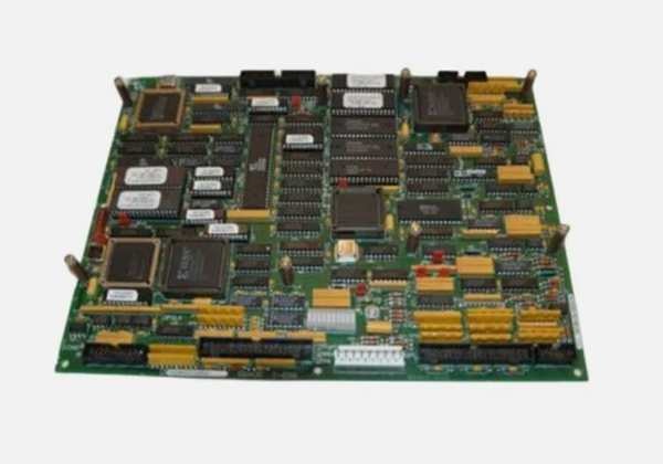
The is a high-performance application controller for GE Mark VIe turbine control systems. It processes complex logic and handles real-time data exchange. This unit replaces older ACLE revisions, offering faster scan times and expanded memory for demanding excitation tasks.
Compared to the H1B, this controller adds 64MB of SDRAM and supports high-density analog I/O. It operates reliably in extreme temperatures up to 75°C. The upgraded processor reduces control loop latency by approximately 15%.
Key Technical Specifications
| Parameter | Value |
|---|---|
| Processor | 1 GHz PowerPC 750FX |
| Cache | 128 KB L2 Cache |
| SDRAM | 64 MB (Expandable) |
| Flash Memory | 4 MB (BIOS/OS Storage) |
| Ethernet Ports | 2 x 10/100 Base-TX RJ45 |
| CANbus Ports | 2 x CANbus Interfaces |
| USB Port | 1 x USB 2.0 |
| SD Card Slot | Yes (For Logging/Recovery) |
| Operating Temp | -25°C to +75°C |
| Storage Temp | -40°C to +85°C |
| Mounting | DIN Rail (2 Half-Slots) |
| Power Input | 24V DC via Backplane |
IS215ACLEH1C
Quality Control Process
- Incoming Verification: Trace serial numbers against GE databases. Check for counterfeit labels and physical damage. Inspect for corrosion on connectors and scratches on PCB.
- Live Functional Test: Power-on with a Fluke 115 multimeter for voltage checks. Establish comms handshake via Modbus TCP. Run continuous load for 36 hours with temperature logging.
- Electrical Parameter Test: Measure insulation resistance with a 500V Megger (must exceed 10 MΩ). Verify ground continuity to chassis.
- Firmware Verification: Read and record firmware version. Photograph all DIP switch and jumper settings for backup.
- Final QC & Packaging: Seal in anti-static bag. Apply QC Passed label with date. Pack with foam padding.
Replacement Pitfall Guide
❗ Firmware Mismatch: New module firmware may be incompatible with older ToolboxST versions. Always verify compatibility before flashing.
❗ DIP Switch / Jumper Misconfiguration: Factory defaults rarely match field settings. Check the bus termination resistor jumper.
❗ Terminal / Cable Incompatibility: Pin definitions can shift between revisions. Verify shield grounding on the third terminal block.
❗ Power Supply Mismatch: Calculate total rack power draw. Maintain 20% headroom above peak load.
❗ ESD Damage: Use an anti-static mat. Dry winter air increases failure risk during handling.
Keep these in mind and you’ll cut 90% of rework time.
Compatibility Matrix & Benchmarks
- IS215ACLEH1B → : Direct — Requires firmware update to v05.01+
- IS215ACLEH1A → : Needs Adaptation — Hardware key change needed
- IS215ACLEH1BC → : Direct — Pinout compatible, higher memory
- Scan cycle: 0.8 ms (simulated load, 128 I/O points)
- Comms throughput: 95 Mbps (TCP/IP protocol)


