

Description
Key Technical Specifications
| Parameter | Value |
|---|---|
| Input Voltage | P28 (28V DC nominal) via backplane |
| Operating Temp | -30°C to +65°C (Typical for Mark VIe accessories) |
| Storage Temp | -40°C to +85°C |
| Output Voltage | +15V DC / -15V DC (For servo current regulators) |
| Current Capability | Supports servo outputs up to -120 to +120 mA DC |
| LVDT Excitation | 7.14V AC, 127 mA AC, 3.2 kHz |
| Speed Sensor Power | 24V DC, 40 mA DC |
| Control Interface | Configurable gains (up to five levels); interfaces with PSVO modules |
| Communication | High-speed Backplane Bus (PDH/VME64x) |
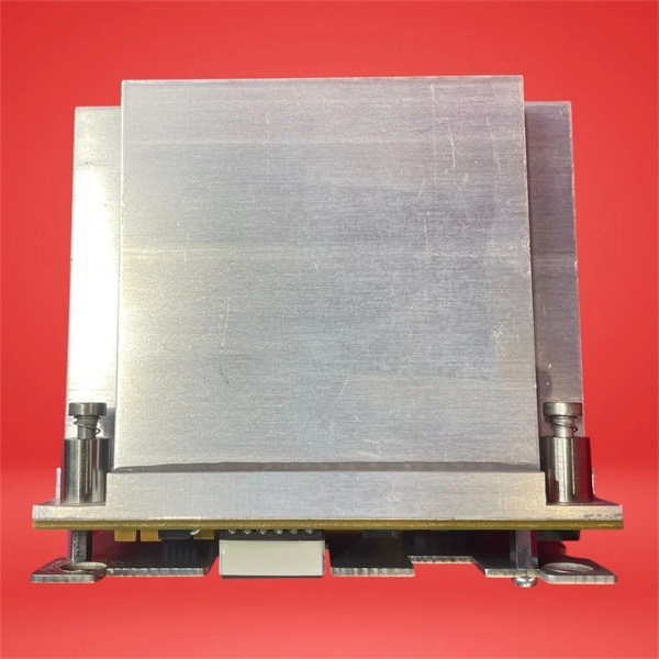
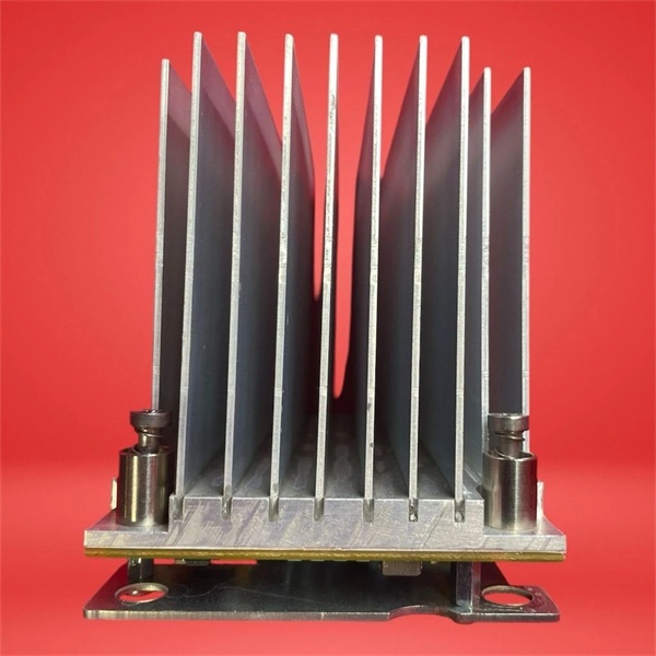
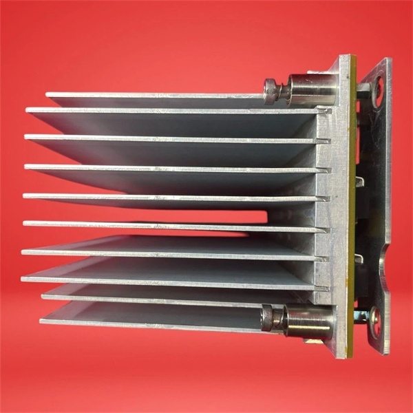
| Mounting | Secured via four screws; includes integrated heatsink for thermal management |
| Connectors | Three J2 connectors (R, S, T) for TMR/Simplex configurations |
| Protection | Servo suicide relays for fault isolation; solid-state switches |
| Compliance | IECEx, UL recognized components, CE |
IS210WSVOH1AE
Product Introduction
The is a mission-critical Servo Driver Board Assembly engineered by GE for its renowned Speedtronic Mark VI and Mark VIe turbine control platforms. Unlike standard driver boards, the “E” revision often signifies a specific hardware configuration or a heatsink-integrated assembly designed for demanding power conversion tasks within the servo control loop.
Positioned at the interface layer between the I/O pack (such as the IS220PSVOH1B) and the physical servo valves, this module accepts the nominal 28V DC system power and generates isolated, highly regulated ±15V rails required by the servo current regulators. Furthermore, it houses the drive circuitry for LVDT (Linear Variable Differential Transformer) excitation, providing the precise 3.2kHz AC signal necessary for accurate valve position feedback. With its robust surface-mount construction, conformal coating, and integrated thermal management, the ensures that heavy-duty gas and steam turbine actuators respond predictably and precisely to control commands, even under extreme environmental conditions.
Key Selling Points & Differentiators
- Precision Power Conditioning for Servo Loops: Delivers clean, regulated ±15V DC power to the servo current regulators, ensuring ultra-stable valve positioning and eliminating control jitter caused by power supply fluctuations.
- Integrated LVDT Excitation Circuitry: Generates a highly stable 7.14V AC, 3.2kHz excitation signal for LVDTs, enabling the control system to accurately read valve stem positions and maintain tight closed-loop control.
- Triple Modular Redundant (TMR) Support: Equipped with three distinct J2 connectors (R, S, T), allowing seamless integration into TMR architectures for high-availability turbine control schemes.
- Advanced Fault Isolation: Features “servo suicide relays” and solid-state switching mechanisms that automatically isolate faulty channels or short circuits, preventing a single-point failure from taking down the entire turbine control loop.
- Rigorous Validation & Burn-In: Each refurbished unit undergoes a stringent 48-hour dynamic load test. We validate the ±15V DC rail stability under varying loads, verify the 3.2kHz LVDT excitation waveform integrity, and cycle the suicide relays to ensure proper fault isolation. Includes a serialized test report and a 12-month warranty.
- Immediate Dispatch: We maintain a specialized inventory of Mark VIe accessory boards and assemblies. New surplus and tested units are ready for 24-hour worldwide shipping to meet your emergency outage and planned maintenance needs.
FAQ
- Its core function is to act as a power conditioning and driver assembly for servo control loops. It steps down the 28V DC input to regulated ±15V DC to power the servo current regulators and provides the necessary excitation signals for LVDT position feedback sensors.
- How does this module differ from the standard IS210WSVOH1A?
While both belong to the WSVO family, the “E” suffix typically denotes a specific hardware revision, a bundled heatsink assembly for enhanced thermal management, or a configuration tailored for specific exciter applications. Always verify the exact compatibility with your existing Mark VIe rack configuration before ordering.
- What happens if the LVDT excitation circuit fails?
If the LVDT excitation fails, the control system loses its ability to accurately determine the physical position of the turbine’s fuel or inlet guide vanes. This will typically force the valve to fail-safe position (usually closed) and trip the turbine to prevent overspeed or over-fueling.
- Is this module hot-swappable?
The is generally part of a larger I/O pack assembly. If your specific I/O pack configuration supports redundant controllers and hot-swapping, it can be replaced online. However, due to the presence of inductive loads and sensitive analog circuitry, always consult your site’s Lockout/Tagout (LOTO) procedures and GE’s official documentation before attempting any live maintenance.
- Does the 12-month warranty cover issues related to site power surges?
The warranty covers hardware failures under normal operating conditions. While the module features robust solid-state protection and suicide relays to isolate faults, claims related to catastrophic power surges or lightning strikes may require a failure analysis to determine the exact cause.

IS210WSVOH1AE
Quality Transparency SOP
- Incoming Verification: Serial number traceability and cross-referencing against GE databases. Comprehensive visual inspection under magnification for burnt components, cracked solder joints, or damaged connectors (especially the R/S/T J2 connectors).
- Functional Bench Test: Mounted in a dedicated Mark VI/VIe test rig. Input power (28V DC) is applied, and the output rails (+15V/-15V DC) are verified under static and dynamic loads. The 3.2kHz LVDT excitation output is checked using an oscilloscope for waveform purity and amplitude accuracy.
- Signal Integrity & Stress Testing: Subjected to a continuous 48-hour stress test, including thermal cycling and forced fault injection (triggering the suicide relays) to ensure the fault isolation mechanisms engage correctly without damaging the rest of the control loop.
- Firmware/Config Verification: Current hardware revision and jumper configurations are documented. Any onboard non-volatile configuration is backed up.
- Final QC & Packaging: Final quality control sign-off completed and dated. Sealed in a custom anti-static bag with moisture absorption packets. Shipped in reinforced cardboard packaging with industrial-grade foam padding to prevent transit damage.
Transparency required: Test reports and video evidence of the bench tests are available upon request. We maintain a strict policy of never claiming “100% failure-free” as all industrial electronic components naturally degrade over time and under operational stress.
Technical Risk Avoidance
Improper TMR Jumper Configuration (R/S/T Voting)
Risk: The features three J2 connectors (R, S, T) designed for TMR configurations. Incorrectly wiring or jumpering these channels in a Simplex system (or vice versa) can lead to a loss of redundancy, spurious trips, or a complete failure to communicate with the servo valve.
Prevention: Always verify the existing wiring and jumper configurations on the faulty module before removal. Match the new module’s setup exactly to the system’s baseline architecture documented in the turbine’s control narratives.
Anecdote: A site engineer replaced a WSVO board in a TMR setup but accidentally crossed the R and T feedback wires on the terminal block. During a routine load swing, the mismatched feedback caused the TMR voter to see a 2-out-of-3 disagreement, forcing the turbine into a manual control mode and triggering an unplanned trip.
Overlooking the Integrated Heatsink Integrity
Risk: The “E” variant often includes an integrated heatsink for thermal management during high-current operations. If the heatsink is damaged during shipping, or if the thermal paste has dried out on a refurbished unit, the module can quickly overheat and go into thermal shutdown during peak turbine loads, causing a sudden loss of valve control.
Prevention: Before installation, inspect the heatsink for bent fins or damage. When mounting, ensure the four securing screws are torqued to spec to maintain proper thermal contact with the chassis or cooling plate.
Anecdote: A technician forced a WSVO board with a slightly bent heatsink mounting tab into the rack. The poor thermal contact caused the board to overheat during a summer heatwave. The resulting thermal throttling caused the fuel valve to become unresponsive, leading to a turbine trip on “Fuel Control Deviation.”
Electrostatic Discharge (ESD) During Handling
Risk: The contains highly sensitive surface-mount DSPs, precision analog-to-digital converters, and LVDT excitation circuitry. Handling the board without proper grounding can cause latent ESD damage that may not surface until the turbine undergoes a high-vibration event or a rapid temperature change.
Prevention: Never handle the module outside of an ESD-safe workstation. Always wear a grounded anti-static wrist strap and handle the board strictly by its metal mounting brackets or designated plastic edges.
Anecdote: A contractor replaced the board on a dry winter morning without using a wrist strap. The new board passed all initial ToolboxST diagnostics. However, two weeks later during a cold snap, the increased electrical noise from the plant caused the board’s LVDT demodulator to misinterpret the valve position, resulting in a violent valve “hunt” and a forced outage for mechanical inspection.
Practical Summary: Treat the as the vital link between your controller’s logic and the physical movement of your turbine’s valves. Always double-check your R/S/T wiring against the TMR configuration drawings, ensure the heatsink is intact and properly mounted for thermal dissipation, and strictly adhere to ESD safety protocols. Keeping the serialized test report on file will ensure a smooth audit trail and protect your warranty.


