
Description
Key Technical Specifications
| Parameter | Value |
|---|---|
| Input Voltage | 24V DC (±10%) / 5V DC (±5%) via Backplane |
| Operating Temp | -20°C to +60°C (-4°F to 140°F) |
| Storage Temp | -40°C to +85°C |
| Max Output Current | 15A Peak (10A Continuous) |
| PWM Frequency | 20kHz (Adjustable) |
| Control Bandwidth | 1kHz (Typical) |
| Resolution | 16-bit |
| Update Rate | 62.5μs (16kHz) |
| Feedback Inputs | Supports 2x Pulse-Rate Sensor Signals (for LVDTs/Resolver feedback) |
| Communication | High-speed Backplane Bus (PDH/VME64x) |
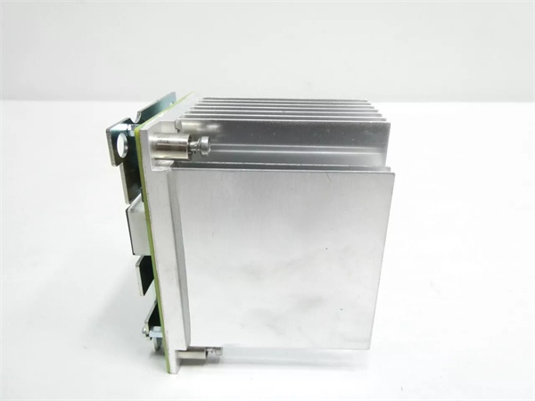
| Mounting | Standard Panel Mount (Equipped with robust metal backplane) |
| Protection | Optical Isolation, Over-current & Thermal Protection |
| Compliance | CE, UL 508, RoHS |
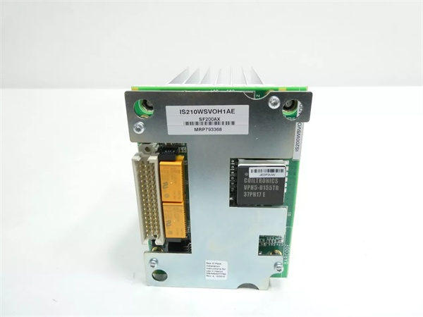
IS210WSVOH1A
Product Introduction
The is a high-performance Servo Driver Board engineered by GE for its renowned Speedtronic Mark VI and Mark VIe turbine control platforms. As a critical interface between the digital controller and the physical hydraulic or electric servo valves, this module translates low-power digital control signals into high-current PWM (Pulse Width Modulation) drive signals capable of precisely positioning heavy-duty turbine actuators .
Designed to thrive in the extreme conditions of power generation and heavy industrial environments, the features a robust metal backplane for secure mounting and enhanced thermal dissipation . With its 16-bit resolution, 20kHz PWM frequency, and support for dual pulse-rate feedback sensors, it ensures ultra-smooth, highly accurate valve positioning—minimizing mechanical wear and optimizing turbine efficiency . Its high reliability and robust design make it an indispensable component for maintaining optimal turbine performance and minimizing costly downtime.
Key Selling Points & Differentiators
- Precision High-Current Valve Control: Delivers up to 15A peak current output with 16-bit resolution and adjustable 20kHz PWM, ensuring ultra-precise positioning of fuel valves, inlet guide vanes (IGVs), and other critical turbine actuators .
- Flexible Gain Configuration: Features five jumper-selectable gain levels, allowing technicians to fine-tune valve response characteristics to perfectly match specific system and load requirements .
- Advanced Feedback Integration: Accepts and processes two pulse-rate sensor signals (compatible with LVDTs and resolvers) to provide real-time position/speed feedback for closed-loop control and enhanced system stability .
- Comprehensive Fault Diagnostics: Continuously monitors system health, providing real-time detection and alerts for calibration faults, LVDT excitation loss, sensor discrepancies, and current feedback errors .
- Rigorous Validation & Burn-In: Every refurbished unit undergoes a stringent 48-hour dynamic load test within a live Mark VI/VIe rack simulator. We validate PWM output accuracy, gain settings, feedback loop response, and thermal performance under max load. Includes a serialized test report and a 12-month warranty.
- Immediate Dispatch: We maintain a large stock of new surplus and tested refurbished units in our distribution centers, ready for 24-hour shipping to meet your urgent replacement needs.
FAQ
- Its core function is to act as a Servo Driver Board. It receives digital control commands from the Mark VIe processor and converts them into high-power PWM signals to drive electro-hydraulic servo valves. It also processes feedback from pulse-rate sensors to ensure accurate valve positioning .
- Is this module compatible with both Mark VI and Mark VIe systems?
Yes, the is designed for seamless integration into both GE Speedtronic Mark VI and Mark VIe turbine control system architectures .
- What types of actuators or valves can this module control?
It is specifically designed to control high-current electro-hydraulic servo valves commonly found in heavy-duty gas and steam turbines, such as fuel metering valves and Inlet Guide Vane (IGV) actuators .
- How does the module protect itself and the connected valves from faults?
The features comprehensive built-in diagnostics that continuously monitor for over-current, thermal overload, LVDT excitation loss, and feedback discrepancies. It also utilizes optical isolation to protect the sensitive backplane logic from electrical noise and transients .
- Does the 12-month warranty cover issues related to incorrect gain jumper settings?
The warranty covers hardware failures of the module under normal operating conditions. However, physical damage to the module’s output stages caused by incorrect jumper settings (leading to excessive gain and current spikes) or improper external wiring may void the warranty.
- Can I replace the module without powering down the entire rack?
If your Mark VI/VIe rack is configured with redundant controllers and supports hot-swapping, yes. However, because this module drives high-power inductive loads, you must always verify your specific system’s redundancy configuration and follow strict ESD safety protocols and Lockout/Tagout (LOTO) procedures before attempting a live swap.

IS210WSVOH1A
Quality Transparency SOP
- Incoming Verification: Serial number traceability and cross-referencing against GE databases. Comprehensive visual inspection under magnification for burnt components, cracked solder joints, or damaged terminal blocks/connectors.
- Functional Bench Test: Mounted in a dedicated Mark VI/VIe test rig. Power-on self-test (POST) monitored via ToolboxST. All PWM output channels are tested under dynamic load conditions using precision electronic loads to verify current capability, frequency response, and waveform integrity.
- Signal Integrity & Stress Testing: Subjected to a continuous 48-hour dynamic load test, including simulated feedback loops (pulse-rate sensors), forced fault injection (disconnected feedback, over-current), and thermal imaging to validate heatsink performance and watchdog timer functionality.
- Firmware/Config Verification: Current firmware version recorded. All jumper (gain/output type) configurations are documented and backed up.
- Final QC & Packaging: Final quality control sign-off completed and dated. Sealed in a custom anti-static bag with moisture absorption packets. Shipped in reinforced cardboard packaging with industrial-grade foam padding to prevent transit damage.
Transparency required: Test reports and video evidence of the bench tests are available upon request. We maintain a strict policy of never claiming “100% failure-free” as all industrial electronic components naturally degrade over time and under operational stress.
Technical Risk Avoidance
Incorrect Gain Jumper (JPx) Configuration
Risk: The uses hardware jumpers to select one of five gain levels for the servo valve output. Setting the gain too high can cause the valve to oscillate or “hunt,” leading to rapid mechanical wear and potential damage to the turbine’s hydraulic actuators. Setting it too low can result in sluggish response during critical turbine transients (e.g., load rejections or startups).
Prevention: Always verify the existing jumper positions on the faulty module before removal. Match the new module’s jumper configuration exactly to the system’s baseline configuration documented in the turbine’s control narratives or logic diagrams.
Anecdote: A maintenance team replaced a failed servo driver board on a steam turbine’s control valve. They guessed the jumper settings, resulting in a gain setting that was twice the specified value. During the subsequent startup, the valve began violently oscillating, causing the turbine to trip on high vibration and requiring a costly mechanical inspection of the valve stem.
Inductive Voltage Spikes During Valve Disconnection
Risk: Servo valves are highly inductive loads. If the wiring to the valve is disconnected or reconnected while the is powered and actively driving the valve, the sudden collapse of the magnetic field can generate a massive voltage spike. This can instantly blow the output stage MOSFETs on the driver board.
Prevention: Always ensure the 24V DC power supply to the servo valve (and the module itself) is turned off and locked out (LOTO) before connecting or disconnecting any field wiring to the terminal block.
Anecdote: An electrician attempted to re-terminate a loose wire on the terminal block of an active WSVO board. The screwdriver briefly shorted the output terminal to ground, causing an immediate arc flash. The resulting voltage spike destroyed the module’s PWM driver chip, turning a simple tightening job into an unplanned $3,000 parts replacement.
Electrostatic Discharge (ESD) During Handling
Risk: The contains sensitive high-speed DSPs, MOSFET drivers, and precision analog feedback circuits. Handling the board without proper grounding can cause silent ESD damage. The module might pass initial diagnostics but fail intermittently when subjected to the electrical noise of the turbine skid during operation.
Prevention: Never handle the module outside of an ESD-safe workstation. Always wear a grounded anti-static wrist strap and handle the board strictly by its metal mounting brackets or plastic edges.
Anecdote: A technician swapped the servo board wearing wool socks on a dry winter day. The new board passed the pre-outage checkout. However, three days later during a cold snap, the increased electrical noise from the plant’s heaters caused the board to misinterpret feedback signals, leading to a spurious turbine trip. Root cause analysis revealed latent ESD damage to the feedback signal conditioning op-amps.
Practical Summary: Treat the as the muscular interface between your controller and your turbine’s hydraulics. Always double-check your gain jumper configurations against the engineering drawings, ensure absolute power isolation before touching the field wiring, and strictly adhere to ESD safety protocols. Keeping the serialized test report on file will ensure a smooth audit trail and protect your warranty.


