
Description
Key Technical Specifications
| Parameter | Value |
|---|---|
| Input Voltage | 125V DC (Nominal, for Trip Solenoids) |
| Operating Temp | 0°C to +60°C (+32°F to +140°F) |
| Storage Temp | -25°C to +70°C (-13°F to +158°F) |
| Trip Solenoids (ETDs) | Interfaces with 3 Solenoids |
| Solenoid Response Time | Defined by L/R time constant |
| Current Suppression | Metal Oxide Varistor (MOV) protected |
| Control Relay Supply | 28V DC (Internal) |
| Flame Detector Supply | 335V DC (For 8x Geiger-Muller detectors) |
| Voting Logic | 2-out-of-3 Hardware Voting (TMR Applications) |
| Communication | I/O Controller Interface (via TTURH1C) |
| Mounting | Panel Mount / Enclosed Chassis |
| Dimensions | Approx. 285 × 170 × 50 mm (11.2 × 6.7 × 2 inches) |
| Weight | 0.9 kg (2.0 lbs) |
| Compliance | CE, UL, Industrial EMC Standards |
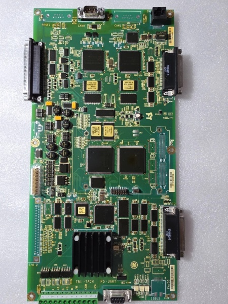
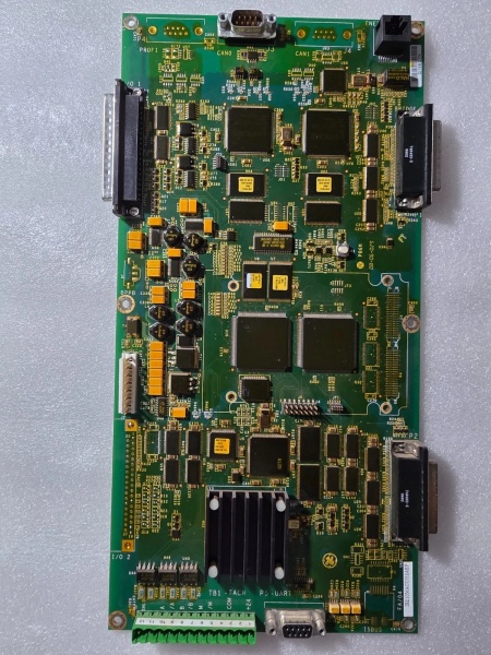
IS210MACCH2A
Product Introduction
The is a mission-critical Primary Trip Terminal Board engineered by GE for its renowned Speedtronic Mark VI and Mark VIe turbine control platforms. As the final hardware enforcement point for turbine protection, this module acts as the crucial interface between the software-based I/O controllers and the physical Emergency Trip Devices (ETDs) .
Specifically designed for heavy-duty gas turbines, the TRPG board manages three primary trip solenoids and accommodates inputs from eight Geiger-Mueller flame detectors . In Triple Modular Redundant (TMR) configurations, it utilizes nine internal magnetic relays arranged in a 2-out-of-3 hardware voting circuit, ensuring that spurious trips are avoided while guaranteeing a shutdown when actual dangerous conditions arise . Built to operate flawlessly in extreme temperatures and high-electrical-noise environments, the delivers the ultimate peace of mind for plant operators needing to safeguard multi-million-dollar rotating equipment.
Key Selling Points & Differentiators
- Hardware-Level TMR Voting: Unlike software-based voting which can be susceptible to scan time delays or processor faults, the executes 2-out-of-3 voting using hard-wired relay logic (nine relays driving three solenoids), providing deterministic and failsafe trip execution .
- Integrated Flame Detection Power: Eliminates the need for external power supplies by providing a dedicated 335V DC supply directly to eight Geiger-Mueller flame detectors, simplifying system architecture and reducing cabinet footprint .
- Comprehensive Built-in Diagnostics: Continuously monitors critical supply voltages and actively tracks the current flow in relay driver lines to detect contact welding, coil failures, or open-circuit wiring before a real emergency occurs .
- Rugorous Validation & Burn-In: Each refurbished unit undergoes a stringent 48-hour dynamic relay cycling test within a live Mark VI/VIe rack simulator. We validate solenoid response times, voting logic integrity, and flame detector power supply stability under load. Includes serialized test report and 12-month warranty.
- Seamless System Integration: Designed to work in perfect harmony with the TTURH1C I/O pack and the TREG (Emergency Trip) board, forming a comprehensive primary and emergency overspeed/process protection barrier .
- Immediate Dispatch: New surplus and tested units are stocked in our distribution center for 24-hour shipping to minimize costly turbine downtime.
FAQ
- It acts as the primary trip interface board. It receives trip commands from the Mark VIe I/O controllers, processes them through hardware voting logic, and drives the physical trip solenoids (ETDs) to shut down the turbine. It also powers and monitors the status of flame detectors .
- Is this module compatible with both Gas and Steam turbines?
While it can be used in various applications, the is specifically optimized for heavy-duty Gas Turbines due to its integrated 335V DC flame detector power supplies and ruggedized design for high-vibration environments .
- How does the module prevent spurious trips?
In TMR systems, the board utilizes a 2-out-of-3 voting mechanism across its nine magnetic relays. A single faulty signal or relay will not cause a nuisance trip; only a confirmed failure (two or more votes) will activate the ETDs .
- What happens if a relay contact welds or fails?
The module features advanced diagnostics that monitor the current flow in the relay driver lines. If a discrepancy is detected between the commanded state and the actual contact status (indicating a welded or open contact), a diagnostic alarm is triggered immediately .
- Does the 12-month warranty cover issues caused by site power surges?
The warranty covers hardware failures under normal operating conditions. Because the module features robust MOVs (Metal Oxide Varistors) for current suppression and surge protection, claims related to catastrophic power surges or lightning strikes may require a failure analysis .
- Can I replace the module without powering down the entire Mark VIe rack?
If your system is configured with redundant controllers and the TRPG is part of a redundant trip loop, it may support online replacement. However, due to the safety-critical nature of this board, always consult your site’s Lockout/Tagout (LOTO) procedures and GE’s official documentation before attempting any live maintenance.

IS210MACCH2A
Quality Transparency SOP
- Incoming Verification: Serial number traceability and cross-referencing against GE databases. Comprehensive visual inspection under magnification for burnt components, cracked solder joints, or damaged terminal blocks.
- Functional Bench Test: Mounted in a dedicated Mark VI/VIe test rig. Power-on self-test (POST) monitored via ToolboxST. All 9 relay outputs are dynamically cycled under load to verify contact resistance and actuation times.
- Signal Integrity & Stress Testing: Subjected to a continuous 48-hour stress test, including voltage transient injections, forced voting scenarios (simulating 1-out-of-3 and 2-out-of-3 conditions), and validation of the 335V DC flame detector power rails.
- Firmware/Config Verification: Current firmware version recorded. All hardware jumper and DIP switch configurations are documented and backed up.
- Final QC & Packaging: Final quality control sign-off completed and dated. Sealed in a custom anti-static bag with moisture absorption packets. Shipped in reinforced cardboard packaging with industrial-grade foam padding to prevent transit damage.
Transparency required: Test reports and video evidence of the bench tests are available upon request. We maintain a strict policy of never claiming “100% failure-free” as all industrial electronic components naturally degrade over time and under operational stress.
Technical Risk Avoidance
Improper TMR Jumper Configuration
Risk: The relies on precise hardware jumper settings to define whether it operates in Simplex or Triple Modular Redundant (TMR) mode. Incorrect jumper placement can disable the 2-out-of-3 voting logic, potentially leading to a nuisance trip (causing unplanned power loss) or, worse, a failure to trip during an actual emergency (risking catastrophic turbine damage).
Prevention: Always verify the jumper positions against the latest system architecture drawings before installing the board. Perform a full “forced-trip” simulation using the ToolboxST software to confirm the voting logic behaves exactly as intended.
Anecdote: A site technician replaced a faulty TRPG board but accidentally left it in the default Simplex jumper configuration while the rest of the turbine protection system was configured for TMR. Two weeks later, a minor sensor glitch—which the voting logic should have ignored—caused an immediate, uncommanded turbine trip, costing the plant millions in lost revenue.
Degraded 125V DC Trip Solenoid Supply
Risk: The TRPG board is highly dependent on a clean, stable 125V DC supply to drive the massive inductive loads of the trip solenoids (ETDs). If the site’s 125V DC battery bank is weak, or if there is significant voltage drop across the distribution terminals, the solenoids may fail to actuate during an emergency shutdown.
Prevention: During preventive maintenance outages, use a calibrated multimeter to verify the 125V DC supply voltage directly at the TRPG’s terminal block (J1) under both quiescent and trip-actuated (loaded) conditions. Ensure all terminations are tight and free of corrosion.
Anecdote: During a routine overspeed test, a gas turbine failed to shut down when the primary trip command was issued. Investigation revealed that severe corrosion on the 125V DC distribution panel had caused a 40-volt drop. The TRPG board commanded the relays to close, but there wasn’t enough voltage to physically pull the heavy ETD solenoids into their trip position.
Electrostatic Discharge (ESD) During Handling
Risk: While the TRPG is a robust power-switching board, its onboard diagnostic microcontrollers and voltage sensing circuits are highly sensitive to electrostatic discharge. Handling the board without proper grounding can cause latent damage that manifests as random “False Flame” or “Trip Solenoid Open” diagnostics weeks later.
Prevention: Never handle the module outside of an ESD-safe workstation. Always wear a grounded anti-static wrist strap and handle the board strictly by its plastic edges or metal mounting brackets.
Anecdote: A contractor replaced a TRPG board on a humid afternoon without using a wrist strap. The turbine started up successfully, but three days later, during a routine load ramp, the system threw a barrage of cryptic “Sensor A/D Error” and “Watchdog Timeout” alarms, forcing a manual trip. The root cause was traced back to microscopic ESD damage on the board’s diagnostic bus.
Practical Summary: Treat the with the highest level of respect, as it is the last line of defense for your turbine. Double-check your TMR jumper configurations, verify your 125V DC supply integrity under load, and strictly adhere to ESD safety protocols. Keep the serialized test report on file for audit trails and warranty claims.


