
Description
Key Technical Specifications
| Parameter | Value |
|---|---|
| Input Voltage | 24V DC (18-32V range) via terminal block (P4) |
| Operating Temp | -25°C to +70°C (-13°F to 158°F) |
| Storage Temp | -40°C to +85°C |
| Input Channels | 18 Channels (Duplex configuration) |
| Signal Type | Analog voltage (Typical ±10V, AC-coupled for dynamic pressure) |
| Outputs | 18 Buffered AC outputs (for external instrumentation) |
| Sensor Support | Compatible with PCB Piezotronics and Endevco sensors |
| Communication | High-speed Backplane Bus (PDH/VME64x) |
| Mounting | DIN Rail or Panel Mount (Chassis compatible) |
| Indicators | 2x LEDs (Run/Communication status) |
| Compliance | CE, UL, Industrial EMC Standards |
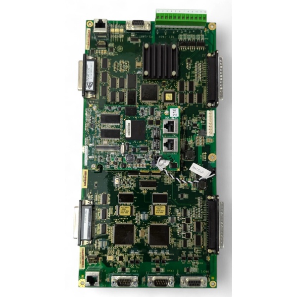
IS210MACCH1AJH
Product Introduction
The is a mission-critical Acoustic Monitoring Terminal Board engineered by GE for its renowned Speedtronic Mark VI and Mark VIe turbine control platforms. Serving as the “auditory nerve” of the turbine, this module is specifically designed to interface with high-frequency microphones and dynamic pressure sensors (such as PCB or Endevco probes) located in the combustion chamber and compressor sections .
By continuously acquiring and conditioning 18 channels of acoustic data, the enables real-time combustion dynamics monitoring, allowing the control system to detect dangerous phenomena like high-frequency resonance, flame instability, or mechanical vibrations before they lead to catastrophic equipment failure . With robust EMI filtering, galvanic isolation, and seamless integration into the Mark VIe architecture, this module ensures the highest levels of availability and protection for heavy-duty gas and steam turbines .
Key Selling Points & Differentiators
- Advanced Combustion Dynamics Monitoring: Features 18 duplex analog input channels capable of capturing high-frequency acoustic and dynamic pressure signals, which is essential for detecting combustion instabilities and preventing hardware damage .
- Flexible Sensor Integration: Equipped with hardware jumpers (JPx) on each channel to independently configure sensor types, supporting both PCB constant-current charge amplifiers and Endevco/CCSA voltage output devices .
- Superior Signal Integrity: Incorporates passive Electromagnetic Interference (EMI) filters on all input channels to eliminate high-frequency noise from external sources, ensuring clean data for the controller .
- Buffered Outputs for Auxiliary Analysis: Provides 18 independent buffered AC outputs, allowing external diagnostic instruments or recorders to monitor combustion dynamics in real-time without disrupting the primary control loop .
- Rigorous Validation & Burn-In: Each refurbished unit undergoes a stringent 24-hour dynamic signal sweep test using precision calibrators to validate frequency response, amplitude accuracy, and EMI filter effectiveness. Includes serialized test report and 12-month warranty.
- Immediate Dispatch: New surplus and tested units are stocked in our distribution center for 24-hour shipping to minimize costly turbine downtime.
FAQ
- Its main function is to act as a terminal board for the Acoustic Monitoring System. It collects high-frequency dynamic pressure and acoustic signals from sensors in the turbine’s hot gas path, conditions these signals, and feeds them to the controller for combustion dynamics analysis .
- What types of sensors can I connect to this module?
The module supports a variety of industry-standard dynamic pressure sensors and microphones, specifically configured via jumpers to support PCB Piezotronics (current-output) and Endevco or GE CCSA (voltage-output) devices .
- How does this module handle electrical noise from the turbine environment?
The is designed with passive EMI filters on all 18 input channels to protect against very high-frequency noise generated by external sources, ensuring reliable data acquisition even in electrically noisy environments .
- Can I use this module for applications other than acoustic monitoring?
While optimized for acoustic and dynamic pressure monitoring in combustion turbines, its 18-channel analog input capability and buffered outputs make it suitable for any application requiring high-speed, high-fidelity analog signal conditioning within the Mark VI/VIe framework.
- Does the 12-month warranty cover issues related to sensor misconfiguration?
The warranty covers hardware failures of the module itself under normal operating conditions. Damage resulting from incorrect external wiring, improper jumper settings leading to electrical overload, or ESD mishandling is excluded.
- Is this module compatible with both Mark VI and Mark VIe systems?
Yes, the is designed for seamless integration into both GE Speedtronic Mark VI and Mark VIe turbine control system architectures .

IS210MACCH1AJH
Quality Transparency SOP
- Incoming Verification: Serial number traceability and cross-referencing against GE databases. Comprehensive visual inspection under magnification for burnt components, cracked solder joints, or damaged terminal blocks.
- Functional Bench Test: Mounted in a dedicated Mark VI/VIe test rig. Power-on self-test (POST) monitored via ToolboxST. All 18 analog input channels are subjected to a dynamic frequency sweep to verify signal conditioning and jumper-configured gain settings.
- Signal Integrity & Stress Testing: Subjected to a continuous 24-hour dynamic load test, including simulated acoustic feedback loops and EMI injection tests to validate filter robustness and watchdog timer functionality.
- Firmware/Config Verification: Current firmware version recorded. All jumper (JPx) configurations are documented and verified against standard acoustic monitoring setups.
- Final QC & Packaging: Final quality control sign-off completed and dated. Sealed in a custom anti-static bag with moisture absorption packets. Shipped in reinforced cardboard packaging with industrial-grade foam padding to prevent transit damage.
Transparency required: Test reports and video evidence of the bench tests are available upon request. We maintain a strict policy of never claiming “100% failure-free” as all industrial electronic components naturally degrade over time and under operational stress.
Technical Risk Avoidance
Sensor Ground Loops & Signal Contamination
Risk: Acoustic sensors and dynamic pressure transducers are highly sensitive to ground potential differences. If the sensor shield is grounded at both the probe and the terminal board, a ground loop occurs, introducing 50/60Hz electrical hum and high-frequency noise into the delicate acoustic signature.
Prevention: Ensure all shielded cables are grounded at only one point (typically the terminal side). Utilize the module’s built-in EMI filters and ensure the 24V DC power supply for the sensors is properly isolated from high-power equipment .
Anecdote: A power plant experienced persistent false positives on their combustion dynamics monitoring, triggering unnecessary turbine derates. The issue was traced to a dynamic pressure sensor whose shield was inadvertently grounded at the compressor casing, creating a ground loop that masked the actual acoustic frequencies.
Incorrect Jumper (JPx) Configuration
Risk: The uses hardware jumpers (JPx) to configure each channel for either PCB (current-output) or CCSA/Endevco (voltage-output) sensors . Setting the jumper incorrectly will result in no signal, clipped/wrong-scale readings, or even damage to the module’s input buffers due to unexpected bias voltages.
Prevention: Before energizing the system, meticulously verify the jumper positions (JP1-JP18) against the sensor type specified in your system’s wiring diagrams. Always double-check the jumper placement when replacing a module.
Anecdote: A technician replaced a failed acoustic board and hastily set the jumpers without consulting the manual. The system used PCB sensors, but the jumpers were left in the CCSA position. This disabled the 3.6mA constant-current source required by the sensors, resulting in zero acoustic data being fed to the controller and a subsequent forced turbine trip during startup.
Electrostatic Discharge (ESD) During Handling
Risk: The sensitive analog front-end components and microprocessors on the can be silently damaged by electrostatic discharge. A module might pass initial POST but fail intermittently when processing high-frequency signals under vibration.
Prevention: Never handle the module outside of an ESD-safe workstation. Always wear a grounded anti-static wrist strap and handle the board strictly by its plastic edges or metal mounting brackets.
Anecdote: An engineer swapped the acoustic monitoring board wearing synthetic clothing on a dry day. The new board appeared functional during the static commissioning test but failed catastrophically two weeks later during a high-load transient event, costing the plant significant revenue.
Practical Summary: Treat the as the critical auditory link between your turbine’s combustion chamber and your control system’s brain. Protect it from ESD, ensure your sensor shielding and jumper configurations are flawless, and leverage its buffered outputs for advanced diagnostics. Keeping the serialized test report on file will ensure a smooth audit trail and protect your warranty.


