

Description
Key Technical Specifications
| Parameter | Value |
|---|---|
| Input Voltage | 24V DC (Nominal, via Backplane) |
| Operating Temp | 0°C to +60°C (32°F to 140°F) |
| Storage Temp | -40°C to +85°C |
| Analog Inputs | Multi-channel for Temp, Pressure, Speed sensing |
| Digital Inputs | Isolated discrete inputs for status/interlocks |
| Analog Outputs | Servo control outputs for actuator regulation |
| Digital Outputs | Relay and solid-state outputs for alarms/control |
| Communication | System Communication Bus (Compatible with Mark VIe rack) |
| Mounting | Rack-mounted / Chassis Slot (Mark VIe) |
| Dimensions | Approx. 150 × 100 × 25 mm |
| Weight | 0.7 kg (1.54 lbs) |
| Compliance | CE, UL, Industrial EMC Standards |
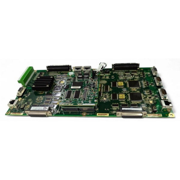
IS210MACCH1AJH
Product Introduction
The is a mission-critical control module engineered by GE for its renowned Speedtronic Mark VIe turbine control platforms. Serving as a primary actuator control board, this module is the nerve center for managing complex signal conditioning, logic processing, and the precise regulation of servo-hydraulic actuators in both gas and steam turbines.
Built to withstand the extreme conditions of power generation environments, the AJH variant features enhanced galvanic isolation and robust noise filtering to ensure deterministic performance amidst high electromagnetic interference (EMI) and mechanical vibration. Whether you are managing a combined-cycle power plant or a heavy industrial turbine, the delivers the reliability and pinpoint accuracy required to keep your rotating equipment operating safely within optimal parameters.
Key Selling Points & Differentiators
- Precision Actuator Regulation: Features dedicated servo control output channels capable of driving hydraulic or electro-hydraulic servo valves with exceptional linearity and minimal deadband, ensuring smooth turbine control surface movements.
- Comprehensive Signal Conditioning: Integrates multi-channel analog and digital I/O with built-in scaling and galvanic isolation, protecting the delicate control logic from field-side electrical noise and transient spikes.
- Advanced Onboard Diagnostics: Continuously monitors sensor health, output loop integrity, and internal processor status. Faults are instantly flagged via the system bus, significantly reducing mean time to repair (MTTR).
- Rigorous Validation & Burn-In: Each refurbished unit undergoes a stringent 24-hour dynamic burn-in test within a live Mark VIe rack simulator. We validate analog output swing, servo response curves, and watchdog timer functionality under load. Includes serialized test report and 12-month warranty.
- Drop-In Compatibility: Designed as a direct replacement for existing Mark VIe racks. Fully recognized by ToolboxST software, eliminating the need for complex hardware key migrations or rack reconfigurations.
- Immediate Dispatch: New surplus and tested units are stocked in our distribution center for 24-hour shipping to minimize costly turbine downtime.
FAQ

IS210MACCH1AJH
- It acts as a main actuator control board. It acquires raw field signals (pressure, temperature, speed), processes them through control logic, and generates precise analog outputs to drive servo valves and other actuators while handling critical interlock protections .
- Is this module compatible with both Gas and Steam turbines?
Yes, the is a versatile control board widely used in GE Mark VIe systems deployed across both gas turbine and steam turbine applications.
- What type of sensors can I connect to this module?
The module supports a wide array of industrial sensors, including 4-20mA transmitters (for pressure/flow), RTDs/thermocouples (for temperature), LVDTs/RVDTs (for valve position feedback), and discrete proximity switches.
- What happens if the module detects a faulty feedback signal?
The module’s built-in self-diagnosis will detect signal anomalies (like out-of-range or disconnected sensors). Depending on your ToolboxST programming, it can trigger an alarm, execute a pre-programmed fail-safe action, or shut down the actuator to prevent mechanical damage.
- Does the 12-month warranty cover issues caused by site power surges?
The warranty covers hardware failures under normal operating conditions. However, because the module features robust surge suppression and isolation , claims related to catastrophic power surges or lightning strikes may require a failure analysis to determine if external protection systems functioned correctly.
- Can I replace the module without powering down the entire Mark VIe rack?
If your Mark VIe rack is configured with redundant controllers and supports hot-swapping, yes. However, always verify your specific rack’s redundancy configuration and follow strict ESD safety protocols before attempting a live swap.
Quality Transparency SOP
- Incoming Verification: Serial number traceability and cross-referencing against GE databases. Comprehensive visual inspection under magnification for burnt components, cracked solder joints, or damaged edge connectors.
- Functional Bench Test: Mounted in a dedicated Mark VIe test rig. Power-on self-test (POST) monitored via ToolboxST. All analog input channels are swept with precision calibrators, and servo outputs are verified under dummy loads.
- Stress Testing: Subjected to a continuous 24-hour dynamic load test, including simulated sensor failures, rapid setpoint changes, and communication bus stress tests to validate processor stability and watchdog timer functionality.
- Firmware/Config Verification: Current firmware version recorded. All jumper and DIP switch configurations are documented and backed up.
- Final QC & Packaging: Final quality control sign-off completed and dated. Sealed in a custom anti-static bag with moisture absorption packets. Shipped in reinforced cardboard packaging with industrial-grade foam padding to prevent transit damage.
Transparency required: Test reports and video evidence of the bench tests are available upon request. We maintain a strict policy of never claiming “100% failure-free” as all industrial electronic components naturally degrade over time and under operational stress.
Technical Risk Avoidance
Ground Loops Causing Signal Drift
Risk: Turbine control systems involve long cable runs from sensors (like LVDTs or temperature transmitters) to the control rack. If these sensors are grounded at the field device and again at the control cabinet, a ground loop occurs, injecting AC noise into your DC control signals. This causes valve hunting or erratic temperature readings.
Prevention: Ensure all analog sensor shields are grounded at only one point (typically the control panel side). Use the module’s built-in galvanic isolation to your advantage by ensuring field power supplies are properly isolated from the main rack power.
Anecdote: A power plant struggled with a steam turbine control valve that would randomly drift. After replacing the twice, an engineer discovered the LVDT feedback shield was grounded at both ends, creating a ground loop that overwhelmed the analog input.
Electrostatic Discharge (ESD) During Handling
Risk: The contains highly sensitive CMOS and processor components. Walking across a carpet and touching the module’s edge connector can silently fry the input buffers. The module might pass initial POST but fail intermittently weeks later under vibration.
Prevention: Never handle the module outside of an ESD-safe workstation. Always wear a grounded anti-static wrist strap and handle the board strictly by its plastic edges or metal mounting brackets.
Anecdote: A technician swapped a faulty control board wearing wool socks on a dry winter day. The new board worked for exactly three weeks before failing catastrophically during a critical grid synchronization event, costing the plant millions in lost revenue.
Improper Servo Loop Tuning (Overshoot/Instability)
Risk: When replacing a failed module, technicians often assume the control logic remains perfectly tuned. However, slight variations in component tolerances between the old and new module (even from the same batch) can shift the servo loop gain, leading to overshoot or chronic instability in the actuator.
Prevention: After installing a new , always perform a small step-response test on the associated actuator. Monitor the valve’s reaction to ensure it settles smoothly at the new setpoint without oscillating. Adjust PID gains in ToolboxST if necessary before returning the turbine to full load.
Anecdote: An overnight repair of a gas turbine fuel control module seemed successful. However, the new board had slightly different output characteristics. When the turbine was brought back online, the fuel valve began to hunt violently, tripping the overspeed protection and forcing a full emergency shutdown.
Practical Summary: Treat the as the critical link between your digital control system and your physical turbine hardware. Protect it from ESD, ensure your field wiring is free of ground loops, and always take the time to re-validate your servo loop tuning after installation. Keep the serialized test report on file for audit trails and warranty claims.


