


Description
Key Technical Specifications
| Parameter | Value |
|---|---|
| Input Voltage | 88-132V AC / 105-132V DC |
| Output Voltage | 24V DC Regulated |
| Output Current | 10A Continuous / 15A Peak |
| Operating Temp | -40°C to +70°C |
| Efficiency | >93% (Improved from 1B) |
| Protection Features | Overvoltage, Undervoltage, Short-Circuit, Reverse Polarity, Transient Suppression (IEEE C62.41) |
| Functional Revision | 2B |
| Mounting | DIN Rail or Panel Mount |
| Communication | IONet / SPI Bus for Health Reporting |
| Dimensions | 30.5cm x 15.2cm x 5.1cm (approx) |
| Weight | 1.5kg (approx) |
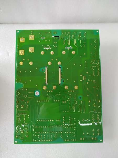
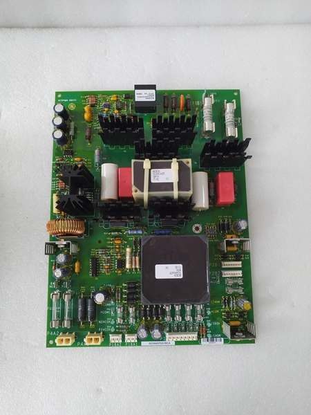
GE IS210AEPSG1AEC
Product Introduction
The represents the latest evolution in GE’s AE Power Supply series, engineered to deliver ultra-stable, noise-free 24V DC power to Mark VIe turbine control systems. As a direct successor to the popular 1B series, the “2B” hardware revision incorporates next-generation silicon, enhanced thermal management, and superior harmonic filtering capabilities.
Procurement specialists and controls engineers specify the 2BB module when modernizing legacy control cabinets or executing new Mark VIe rack builds. It is heavily utilized in power generation, LNG, and heavy industrial compression, where the highest levels of control system uptime are mandatory. The 2BB ensures deterministic output during severe grid fluctuations, effectively decoupling sensitive Mark VIe processors from plant-wide electrical noise.
Key Selling Points & Differentiators
- Enhanced Hardware Stability: The “2B” revision offers improved thermal derating and greater efficiency (>93%) compared to the 1B series, making it ideal for high-ambient temperature environments.
- Forward/Backward Compatibility: Designed to integrate seamlessly into existing racks. While optimized for modern ToolboxST versions, it maintains interoperability with older 1B hardware keys when paired with the correct firmware baseline.
- Rigorous Test Protocol: Every refurbished unit is subjected to a 24-hour continuous burn-in test under dynamic loads. New surplus units are ESD-packaged and backed by a 12-month warranty.
- Not recommended for: Direct substitution in legacy systems running highly outdated firmware without first verifying the hardware key in ToolboxST to prevent boot-up mismatch errors.
- Immediate Dispatch: New surplus and tested refurbished units are stocked in our Houston distribution center for 24-hour shipping.
FAQ
- Can the directly replace an older IS210AEPSG1B?
Yes, the “2B” hardware is designed to be mechanically and electrically backward-compatible. However, we highly recommend verifying the hardware key in your ToolboxST project file to ensure firmware compatibility and prevent controller mismatch errors during boot-up.
- What is the typical lead time if the unit is out of stock?
New surplus units typically have a 2-4 week lead time depending on customs clearance. Tested refurbished units are usually available for immediate shipment within 24 business hours.
- How do I identify a failing power supply in my Mark VIe rack?
Common indicators include intermittent “Controller Lost” alarms, unexpected I/O module resets, or visible bulging on the electrolytic capacitors. Check the controller diagnostics for “Undervoltage Lockout” events.
- Does the 12-month warranty cover firmware corruption?
The warranty covers hardware failures under normal operating conditions. It does not cover issues arising from incorrect firmware uploads, ESD damage during handling, or physical damage from improper installation.
- I am upgrading my ToolboxST software. Will this module still work?
The 2B hardware is fully forward-compatible with modern ToolboxST upgrades. However, significant software updates may require a firmware flash. Consult your lead controls engineer before performing updates.
- What accessories come with the module?
Each unit ships with the original mounting hardware. Terminal blocks and connectors are included if originally part of the assembly. Contact sales if you require additional cabling.
- How is the module tested before shipment?
All units undergo the Quality Transparency SOP outlined below. We utilize a dedicated Mark VIe test rack to simulate real-world load conditions and verify communication integrity.

GE IS210AEPSG1AEC
Quality Transparency SOP
- Incoming Verification: Source traceability check and serial number cross-referencing. Visual inspection for burnt components, corroded pins, or damaged mounting tabs. Accessories count verified.
- Live Bench Test: Mounted on a dedicated test rack with a live Mark VIe controller. Power-on self-check performed. Communications handshake verified via IONet protocol. Full-scale I/O simulation executed. Subjected to a continuous 24-hour load test at maximum rated capacity. Comprehensive timestamped test report generated.
- Electrical Tests: Insulation resistance measured using a 500V megger (must exceed 10 MΩ). Ground continuity strictly verified.
- Firmware Verification: Current firmware version recorded. All DIP switch and jumper configurations documented and backed up.
- Final QC & Packaging: Final quality control sign-off completed and dated. Sealed in an anti-static bag. Surrounded by industrial-grade foam shock protection. Affixed with a “QC Passed” label.
Transparency required: Test photos and video evidence of the bench test are available upon request. We never claim “100% failure-free” as industrial components operate under immense stress.
Technical Risk Avoidance
Firmware/Hardware Key Mismatch
Risk: Installing a “2B” unit into a system expecting a “1B” hardware key without proper firmware alignment will cause a mismatch error, preventing the Mark VIe controller from booting.
Prevention: Always compare the full part number and Hardware Key in your ToolboxST project file before swapping. Update the controller’s hardware definition file if necessary.
Anecdote: An engineer swapped a faulty 1B supply with a new 2B unit but skipped the firmware check. The controller rejected the new hardware, resulting in an unplanned 16-hour turbine downtime.
DIP/Jumper Errors
Risk: Incorrect jumper settings for input voltage (115V vs 230V) will instantly destroy the module upon power-up.
Prevention: Photograph the jumper configuration of the failed unit before removal. Always verify against the official GE technical manual before applying power.
Anecdote: A contractor assumed the default jumpers were correct for a 230V supply. Applying power fried the input stage, causing a loud bang and requiring an emergency procurement at 3x the standard cost.
Terminal Incompatibility
Risk: Using undersized wiring (e.g., 18 AWG) for the 24V DC output causes excessive voltage drop under the 10A load, leading to erratic sensor readings or underpowered solenoids.
Prevention: Use a minimum of 12 AWG stranded copper wire for the main 24V DC output. Torque terminal screws to the specified 0.5 Nm to prevent loosening due to thermal cycling.
Anecdote: An installer used 14 AWG wire for a fuel control valve bank. Over time, the resistance increased due to heating, causing the valve to drift and the turbine to operate inefficiently.
Power Budget Miscalculation
Risk: Connecting too many high-draw solenoids or I/O modules will exceed the 10A continuous rating, forcing the AEPSG into thermal shutdown.
Prevention: Calculate the total worst-case current draw of all connected devices. Ensure the total load does not exceed 80% of the module’s 10A rating (8A max recommended).
Anecdote: An engineer added several new proximity probes to a rack powered by a single AEPSG. The cumulative draw reached 11A, causing the module to overheat and trip intermittently.
ESD Damage
Risk: The internal DSP and logic components are highly sensitive to electrostatic discharge. Casual handling can create microscopic damage that causes intermittent failures weeks later.
Prevention: Always wear a grounded anti-static wrist strap and handle the module only by its edges or designated grounding points.
Anecdote: A technician placed a module on a rubber mat while troubleshooting. The static discharge from his uniform destroyed the communication chip. The module passed the initial bench test but failed to communicate once installed in the rack.
Practical Summary: Match the suffix exactly, verify the hardware key in your software, respect the 10A power budget, and handle with strict ESD protocols. Keep the serialized test report on file for audit trails and warranty claims.


