
Description
Key Technical Specifications
-
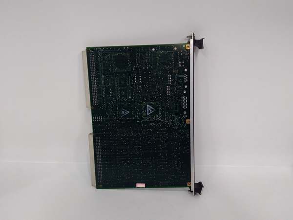
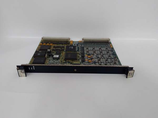
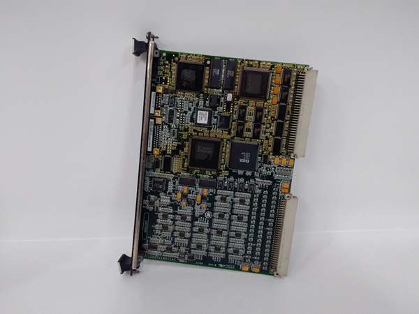
Model Number: IS200VVIBH1C
-
Manufacturer: General Electric (Salem, VA)
-
Probe Support: Bently-Nevada Proximitor, Velomitor, accelerometer, seismic; ±10 V or 4-20 mA jumper-select
-
Channels: 14 diff inputs (expandable to 26 with two TVIB/DVIB terminal boards)
-
Sample Rate: 4.6 kHz per channel (2.3 kHz when >14 ch enabled); 12-bit ADC, FPGA-based peak-detect
-
Probe Power: –28 VDC bus, diode high-select in TMR; individual –23…–26 V, 12 mA current-limited outputs
-
Signal Processing: Max-min peak-detect over 160 ms window, programmable 2- to 8-pole LP/HP/BP filters, 1X/2X Keyphasor tracking
-
Output: Scaled EU peak-to-peak (displacement) or EU pk velocity via VME bus; 0.1 % amplitude accuracy
-
Isolation: 1500 Vrms field-to-logic; 500 V channel-to-channel
-
Connectors: 96-pin DIN VME, two 50-pin ribbon to TVIB/DVIB terminal boards
- Operating Temperature: –20 °C to +70 °C (conformal-coated)

IS200VVIBH1C
Field Application & Problem Solved
A frame-7 peaker doesn’t wait for a bearing to seize—it wants shaft vibration trending in real time. The IS200VVIBH1C lives in the Mark VI VME rack, powers up to fourteen Bently-Nevada proximity probes, digitises the signals at 4.6 kHz, and ships peak-to-peak displacement or velocity to the controller every 100 ms. When the card fails you lose vibration protection, the unit folds to manual, and you’re climbing again; swap the board, snap the two ribbon cables back in, and the trends re-appear exactly as they did on day-one—no re-cal, no firmware flash. Found in every Mark VI cabinet from 50 MW peakers to 400 MW combined-cycle blocks. Value is early warning: 0.1 % amplitude accuracy keeps the API-670 alarm curves honest, so you schedule the outage before the shaft rubs.
A frame-7 peaker doesn’t wait for a bearing to seize—it wants shaft vibration trending in real time. The IS200VVIBH1C lives in the Mark VI VME rack, powers up to fourteen Bently-Nevada proximity probes, digitises the signals at 4.6 kHz, and ships peak-to-peak displacement or velocity to the controller every 100 ms. When the card fails you lose vibration protection, the unit folds to manual, and you’re climbing again; swap the board, snap the two ribbon cables back in, and the trends re-appear exactly as they did on day-one—no re-cal, no firmware flash. Found in every Mark VI cabinet from 50 MW peakers to 400 MW combined-cycle blocks. Value is early warning: 0.1 % amplitude accuracy keeps the API-670 alarm curves honest, so you schedule the outage before the shaft rubs.
Installation & Maintenance Pitfalls (Expert Tips)
Probe power reversed—-28 V on +12 V pin cooks the FPGA
The 50-pin ribbons are keyed alike but pin-outs differ. Land a Proximitor cable on the logic header and you stuff –28 V into the 3.3 V FPGA—smoke show. Match the white wire-stripe to the silk-screen “TVIB-1” arrow before you push the connector home.
The 50-pin ribbons are keyed alike but pin-outs differ. Land a Proximitor cable on the logic header and you stuff –28 V into the 3.3 V FPGA—smoke show. Match the white wire-stripe to the silk-screen “TVIB-1” arrow before you push the connector home.
Gapped steel ring mis-aligned—flux bypasses Hall, fake zero
Channels 1-3 use internal flux concentrators. If the ring gap isn’t centered over the sensor the peak-detect reads zero and you miss a rub. Torque the ring screws to 1 N·m and check the gap with a feeler—0.05 mm offset drops the signal 10 %.
Channels 1-3 use internal flux concentrators. If the ring gap isn’t centered over the sensor the peak-detect reads zero and you miss a rub. Torque the ring screws to 1 N·m and check the gap with a feeler—0.05 mm offset drops the signal 10 %.
Filter type mismatch—velocity reads low on seismic probe
Default filter is 8-pole low-pass @ 200 Hz. If you land a 4-20 mA seismic probe and forget to change FilterType the integrator rolls off early and velocity reads 15 % low. Always match FilterType to sensor in Toolbox-ST before you lock the door.
Default filter is 8-pole low-pass @ 200 Hz. If you land a 4-20 mA seismic probe and forget to change FilterType the integrator rolls off early and velocity reads 15 % low. Always match FilterType to sensor in Toolbox-ST before you lock the door.
IS200VVIBH1C
Conformal coat cracked—salt fog bridges the –28 V bus
The board is coated, but the 50-pin edge is masked. If the coat cracks, salt bridges –28 V to 5 V and you cook the FPGA. Scrape the salt, hit the edge with 2100-FTG, and re-coat—problem gone for another decade.
The board is coated, but the 50-pin edge is masked. If the coat cracks, salt bridges –28 V to 5 V and you cook the FPGA. Scrape the salt, hit the edge with 2100-FTG, and re-coat—problem gone for another decade.
Technical Deep Dive & Overview
IS200VVIBH1C is a 14-channel vibration processor frozen in 2000 silicon. An FPGA runs the 4.6 kHz ADC, performs max-min peak-detect, applies programmable filters, and latches EU data onto the VME bus every 100 ms. Because the card powers the probes and processes the signals you can swap it hot—just kill the –28 V supply first or you’ll arc-weld the 50-pin ribbon. Treat the probe coax like instrumentation cable and the board will keep the shaft vibration trend flat for another thirty years
IS200VVIBH1C is a 14-channel vibration processor frozen in 2000 silicon. An FPGA runs the 4.6 kHz ADC, performs max-min peak-detect, applies programmable filters, and latches EU data onto the VME bus every 100 ms. Because the card powers the probes and processes the signals you can swap it hot—just kill the –28 V supply first or you’ll arc-weld the 50-pin ribbon. Treat the probe coax like instrumentation cable and the board will keep the shaft vibration trend flat for another thirty years
.


