
Description
Key Technical Specifications
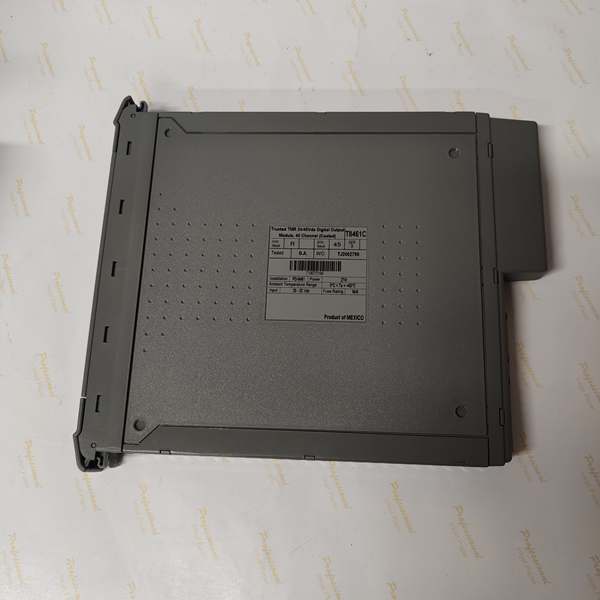
- Core Architecture: Adopts triple modular redundancy (TMR) architecture. Each of the 32 output channels has three identical control switch channels. It achieves fault tolerance through redundant design and can maintain stable operation even if a single circuit fails.
- Electrical Parameters: The system power supply voltage ranges from 20VDC to 32VDC. The field voltage range of the output is 35VDC – 130VDC for versions before revision J35, and 35VDC – 150VDC for revision J35 and later. Each channel can continuously output 0.5A current, and each power group (8 channels as a group, totaling 4 groups) can continuously output 2A current. The minimum on-state load current is 20mA, and the maximum withstand voltage is 200VDC.
- Safety & Isolation: It has obtained TÜV certification and complies with the IEC 61508 SIL 3 standard. It is equipped with a 2500V impulse-resistant photoelectric isolation barrier, which can effectively isolate interference between circuits and ensure the safety of signal transmission. Each channel is equipped with automatic overcurrent protection, so no additional fuses are needed.
- Functional Performance: It supports on-board sequence of events (SOE) reporting with a resolution of 1ms. When the output state changes, it will trigger SOE records immediately. The module can automatically monitor the line to detect open circuit, short circuit faults of field wiring and load faults.
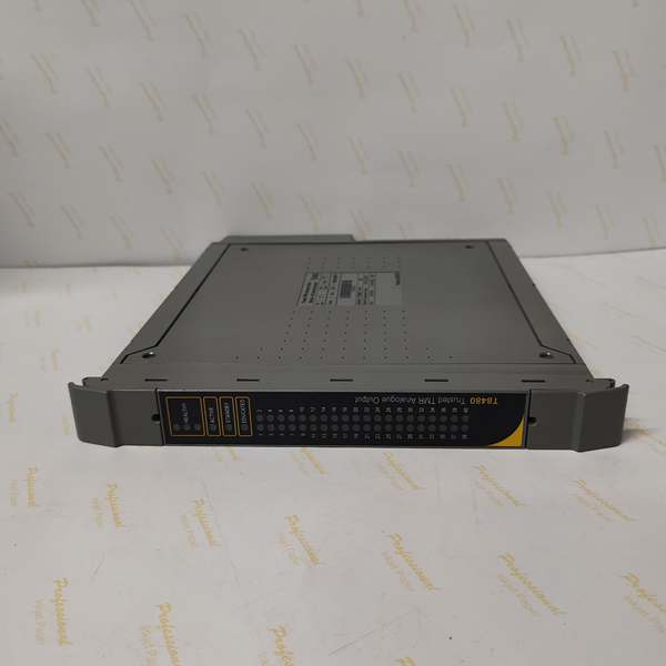
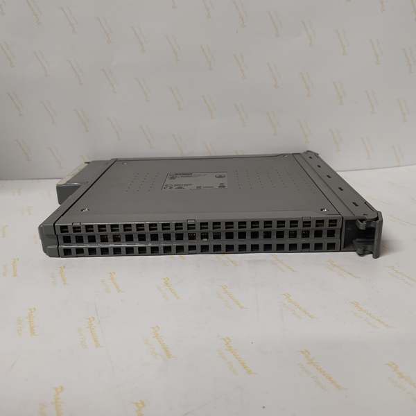
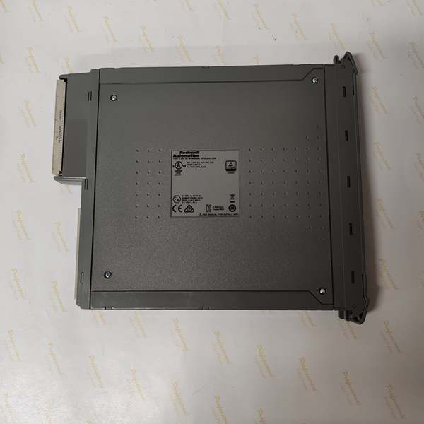
- Physical & Environmental Parameters: The module dimensions are 266mm × 31mm × 303mm and weighs about 1.342kg. It can work in the temperature range of -40°C to 85°C, adapting to the harsh temperature environment of industrial sites.
- Other Features: Supports hot-swappable replacement with the help of adjacent matching modules, which is convenient for maintenance. The front panel is equipped with status indicator lights, which can intuitively display the output status, field wiring faults and module health status.
ICS Triplex T8153C
Field Application & Problem Solved
The T8471 module solves these pain points through its excellent design. In a thermal power plant, it can output control signals to the turbine’s auxiliary system valves. The TMR redundant design ensures that even if one output channel fails, the other two channels can take over the work to avoid sudden shutdown of the turbine. In a petrochemical refinery, it connects 32 sets of emergency shut-off valves in the distillation unit. Once a short circuit occurs in the wiring of a certain valve, the module can quickly detect the fault and send an alarm, and the other channels will not be affected. In water treatment plants, it drives the switch of the water pump control contactor, and its 1ms SOE reporting function can accurately record the action time of each water pump, which is convenient for subsequent operation analysis and fault tracing.
Installation & Maintenance Pitfalls (Expert Tips)
- Power Group Load Matching: The module divides 32 channels into 4 independent power groups. A common mistake during installation is to concentrate high-load equipment on one group. For example, connecting multiple 0.4A high-power solenoid valves to the same 8-channel group will exceed the 2A current limit of the group, resulting in overcurrent protection triggering and affecting the operation of the entire group. It is necessary to distribute high and low load equipment evenly among the 4 groups according to the current rating of the field equipment.
- Wiring Protection Against High Voltage: The module’s later version can withstand up to 150VDC voltage, but the wiring still needs to avoid high-voltage interference. Do not route the output wiring together with high-voltage power cables. When wiring in the same cable tray, use partition plates for isolation. Otherwise, high-voltage transient pulses may break through the isolation barrier and damage the module’s internal circuits.
- Standardizing Hot-Swap Operations: Although the module supports hot-swapping, it must be operated with the help of adjacent matching modules. Many maintenance personnel directly pull out the module during maintenance, which is easy to cause data loss or backplane circuit damage. The correct operation is to first confirm the module’s standby status through the status light, then use the dedicated hot-swap mechanism, and pull out the module after the indicator light shows it is safe to remove.
- Reasonable Utilization of Diagnostic Information: The module has a powerful diagnostic function, but some users ignore the analysis of diagnostic data. When the fault light is on, they only simply replace the module. In fact, the module can detect faults such as open circuits, short circuits and stuck outputs. It is necessary to use the upper computer software to read specific diagnostic reports to find out whether the fault is from the module itself, the field wiring or the actuator, so as to avoid repeated replacement of the module and increase maintenance costs.

ICS Triplex T8153C
Technical Deep Dive & Overview
In terms of signal security, the 2500V high-voltage isolation design is a highlight. It can resist the electromagnetic interference generated by high-power equipment such as motors and inverters in industrial environments, and avoid false actions of actuators caused by signal distortion. The per-channel overcurrent protection is also a practical design. In the case of accidental short circuits of field equipment, it can cut off the current in time to prevent the module from being burned out, reducing the loss of equipment maintenance.
The 1ms resolution SOE reporting function is of great significance for safety-critical systems. In the event of an industrial accident, the accurate time record of each output action can help technicians trace the sequence of events, analyze the cause of the accident quickly, and formulate targeted improvement measures. Meanwhile, the front-panel indicator lights allow on-site operators to quickly grasp the module’s operating status without connecting diagnostic tools, which shortens the preliminary troubleshooting time.
In terms of system integration, the module can be seamlessly connected with the ICS Triplex Trusted series controllers. It does not require complex protocol conversion and can be configured and managed through the IEC 1131 toolset software. This not only reduces the difficulty of system construction but also ensures the compatibility and stability of the entire control system. For enterprises that pursue high reliability and safety in production, the T8471 is not just a simple digital output module, but a key component to ensure the continuous and safe operation of critical processes.


