
Description
Hard-Numbers: Technical Specifications
-
Protocol Support: TriStation 1131, Modbus TCP/IP (via system integration), proprietary Trusted IMB bus
-
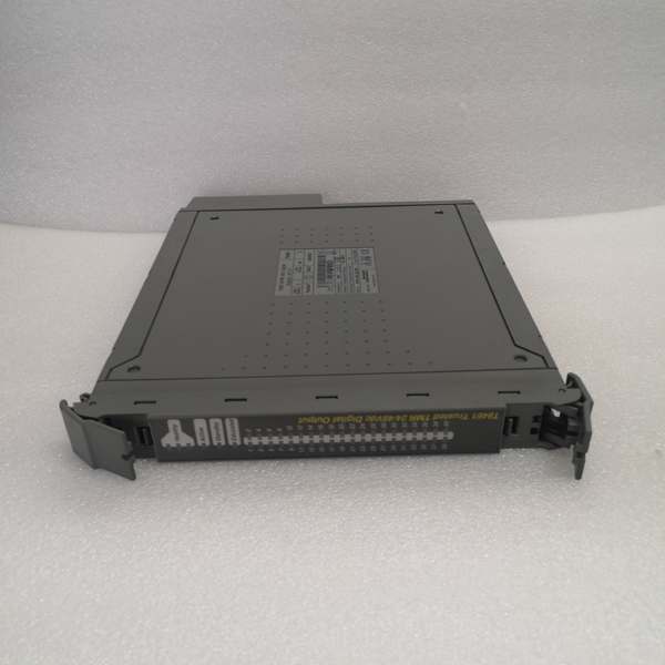
Output Channels: 40 TMR digital outputs (5 isolated power groups × 8 channels each)
-
Output Voltage Range: 18 Vdc to 60 Vdc (field-side), 24/48 Vdc nominal
-
Output Current: 0.75 A continuous per channel, 6 A max per power group
-
Minimum Load Current: 25 mA (on-state)
-
On-State Resistance: 1.6 Ω max
-
Response Time (On/Off): 0.5 ms
-
SOE Resolution: 1 ms timestamp accuracy ±10 ms
-
Operating Temperature: -5°C to +60°C (standard), -40°C to +70°C (extended variants)
-
Isolation Rating: 250 Vdc continuous working (field common), 2.5 kVdc withstand test, 50V reinforced between power groups
-
Power Draw: 26W (system supply), up to 36W field supply at max load
-
System Supply Voltage: 20-32 Vdc
-
Short Circuit Protection: Electronic latching (self-resetting after fault clearance)
-
Safety Certification: IEC 61508 SIL 3, TÜV certified

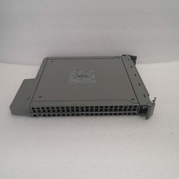
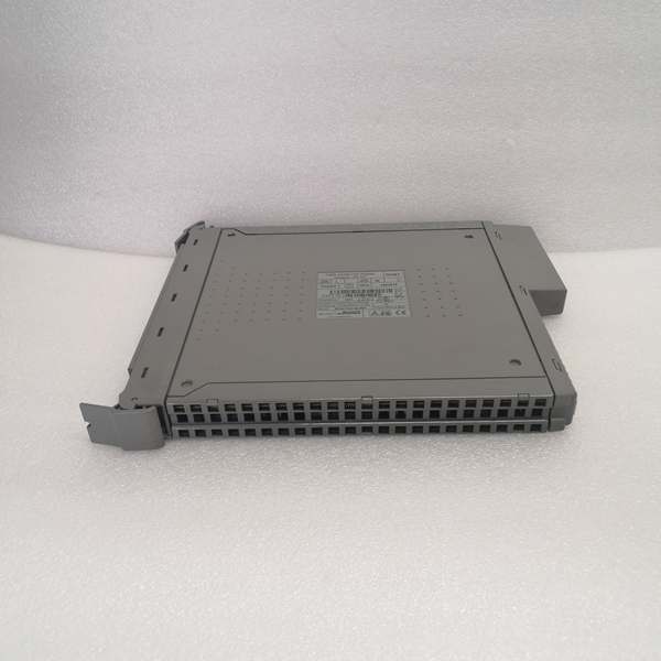
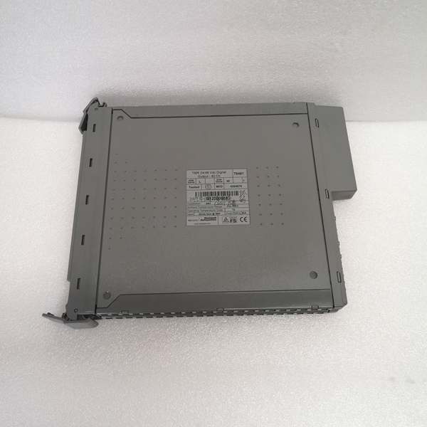
ICS TRIPLEX T8461
The Real-World Problem It Solves
A stuck-open solenoid valve or welded relay contact in a Safety Instrumented System isn’t just a maintenance headache—it’s a potential fatality waiting to happen. The T8461 eliminates the “single point of failure” nightmare that keeps safety engineers awake at night by running three independent output circuits in parallel and voting the results. If one channel goes rogue (stuck high, stuck low, or intermittent), the other two out-vote it and the process stays safe.
Where you’ll typically find it:
-
Emergency Shutdown (ESD) valve manifolds on offshore platforms and refinery units
-
Fire & Gas (F&G) system actuator controls in petrochemical plants
-
Turbine trip solenoids and boiler burner management systems (BMS)
This module keeps your SIS online even when hardware fails—no spurious trips, no dangerous failures, just hardcore fault tolerance.
Hardware Architecture & Under-the-Hood Logic
The T8461 isn’t just a dumb relay board—it’s a self-monitoring intelligent node on the Trusted IMB (Inter-Module Bus) backplane. Each channel contains three independent microprocessor-controlled output drivers that execute the same command simultaneously. The module performs continuous self-diagnostics and line monitoring without external test equipment.
Internal Signal Flow:
-
Command Reception: TriStation 1131 logic downloads output states via the IMB backplane to the module’s three independent processors (A, B, C channels)
-
2oo3 Voting: Each processor drives its own output transistor; the three outputs are wired in series-parallel configuration requiring two-of-three agreement to energize the field device
-
Line Monitoring: Onboard circuitry continuously checks for open circuits (broken field wires) and short circuits (stuck loads), differentiating between field-side and module-side faults
-
Current/Voltage Sensing: Each channel measures actual load current (0-1.35A range) and field voltage (0-58Vdc) with ±5% accuracy for drift detection
-
SOE Timestamping: State changes are latched with 1ms resolution and queued for retrieval by the safety controller for post-trip analysis
-
Fault Annunciation: Discrepancies between voted channels trigger module health bits and front-panel LED indicators without de-energizing good outputs
ICS TRIPLEX T8461
Field Service Pitfalls: What Rookies Get Wrong
Ignoring the 25mA Minimum Load Requirement
Many junior techs wire the T8461 to high-impedance inputs or small pilot relays and wonder why the “Output On” LED is lit but nothing happens. The module’s line monitoring circuitry requires at least 25mA of load current to verify circuit continuity. Below this threshold, the channel reports an open-circuit fault even if the wiring is intact.
-
Field Rule: Always verify your load draws >25mA in the energized state. If driving a high-impedance device, install a bleeder resistor (typically 1kΩ, 2W) across the output terminals to sink sufficient current.
Mixing Power Group References
Each group of 8 channels (Power Groups 1-5) has isolated field commons. Novices often tie all field commons together in the junction box, defeating the isolation and creating ground loop paths between power groups. This can cause cross-talk faults and nuisance trips when one group faults.
-
Quick Fix: Keep power group commons separate all the way back to the power supply. Use distinct terminal blocks or color-coded wiring (e.g., Group 1 = red, Group 2 = blue) and never bridge them in the field. Check isolation with a megger before commissioning.
Assuming “Hot-Swappable” Means “Hot-Plug Without Precautions”
Yes, the T8461 supports online replacement via Companion Slot or SmartSlot architecture—but only if the system is configured for it. Pulling a module from a simplex configuration or during a critical voting sequence can bump the SIS offline.
-
Field Rule: Always verify the chassis is running redundant processor modules (T8151B/T8153B) and the replacement slot is designated as a Companion Slot before extracting the old module. Check the “MODULE HEALTH” LED pattern—steady green means safe to remove; flashing red means wait for the vote to settle.


