
Description
Hard-Numbers: Technical Specifications
- Channel Count: 32 isolated digital input channels
- Input Type: 24VDC wetting voltage (sourcing/sinking configurable)
- Input Voltage: 20.4–27.6VDC nominal; 18–30VDC operating range
- Input Current per Channel: 4–10 mA typical for 24VDC wetting
- Input Resistance: ~2.4 kΩ per channel
- Channel Isolation: 1500VAC channel-to-channel isolation
- Module Isolation: 5000VAC module-to-backplane isolation
- Response Time: <2 ms typical for high-speed safety channels
- Scan Rate: <10 ms module update rate
- Diagnostic Coverage: 99.9% per IEC 61508 (SIL 3)
- Operating Temperature: -40°C to +70°C full load; -40°C to +85°C storage
- Humidity: 10–90% RH non-condensing
- Power Consumption: ~12W typical (varies by channel count)
- Certifications: TÜV SIL 3, ATEX, IECEx, FM, UL
- Dimensions: 208 mm × 120 mm × 55 mm (8.2″ × 4.7″ × 2.2″)
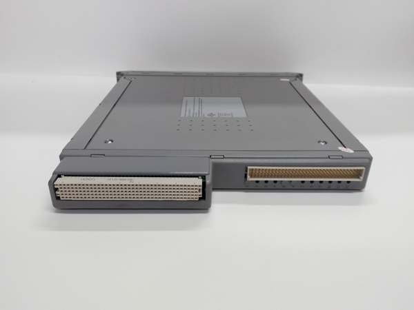
- Mounting: Hot-swappable in Tricon/Tricon CX chassis slots
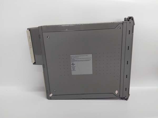
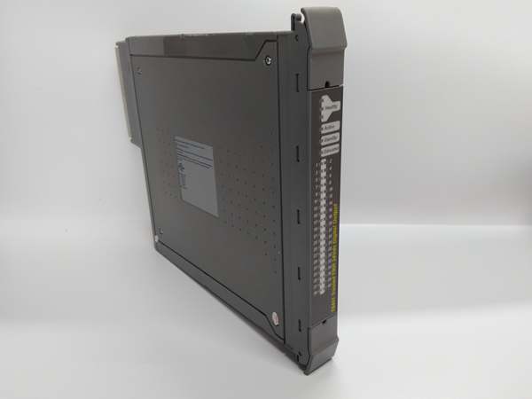
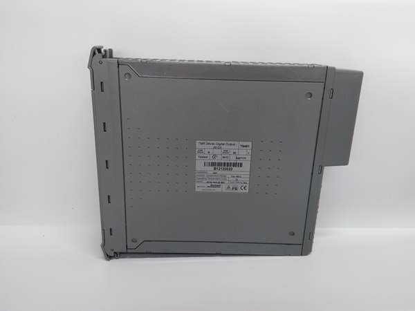
ICS TRIPLEX T8451
The Real-World Problem It Solves
Large safety systems often have hundreds of discrete inputs—limit switches, pressure switches, valve position feedback, pushbuttons. Using standard 8-channel or 16-channel input modules fills chassis slots quickly, leading to expanded cabinets and higher costs. The T8451 packs 32 isolated digital input channels into a single module, doubling the density of typical 16-channel modules while maintaining full SIL 3 compliance. Each channel is fully isolated, and comprehensive diagnostics detect wire breaks, shorts, and signal degradation on all 32 channels simultaneously.
Where you’ll typically find it:
- Tricon/Tricon CX systems with high-density discrete input requirements (ESD systems with numerous limit switches)
- Process safety applications requiring high channel count without expanding cabinet space
- Large-scale shutdown systems where channel density and diagnostic coverage are critical
Bottom line: The T8451 delivers twice the channels in the same space—saving cabinet slots, reducing wiring complexity, and keeping diagnostics high.
Hardware Architecture & Under-the-Hood Logic
The T8451 is an enhanced 32-channel digital input module designed for the Tricon and Tricon CX safety platforms. It slides into the Tricon chassis and communicates with the Tricon controller via the backplane. Inside, it features a redundant dual-processor architecture with fully isolated channel input circuitry for all 32 channels. The module uses high-density multiplexing for backplane communication but maintains individual channel isolation and diagnostics for SIL 3 compliance.
-
Channel Input Circuitry: Each of the 32 channels has an opto-isolation barrier providing 1500VAC channel-to-channel isolation, preventing fault propagation between channels. The input is configurable as sourcing or sinking via DIP switch settings (global per channel bank). For each channel, the module applies a wetting voltage (24VDC) to dry contact inputs or monitors current for active inputs. Channels are organized in banks of 8, each bank sharing common configuration.
-
Dual Redundant Processing: The module contains two independent microcontroller-based processing chains that simultaneously read and validate each of the 32 input channels for SIL 3 compliance. Both chains continuously compare their results to ensure consistency. If Chain A and Chain B disagree on any channel state, a diagnostic fault is immediately flagged. The Tricon controller automatically takes predefined action—bypassing the faulty channel while keeping healthy ones online or triggering safety interlocks based on severity.
-
Comprehensive Diagnostics: The module runs continuous, channel-level diagnostics on all 32 inputs, including:
- Wire break detection via voltage or current sensing
- Short circuit detection (line-to-line or line-to-ground)
- Stuck-at-0 or stuck-at-1 fault detection
- Input signal integrity checks (out-of-range voltage/current)
- Channel-to-ground isolation monitoring
- Module-to-backplane isolation testing (periodic self-test)
- Channel-to-channel isolation verification (periodic test)
-
High-Density Backplane Communication: The T8451 uses multiplexed communication to transmit 32 channels of data over the Tricon backplane efficiently. This reduces backplane bandwidth usage while maintaining fast scan rates (<10 ms). The module buffers channel states and transmits them in packets to the Tricon controller. Despite multiplexing, each channel maintains its own isolation barrier and diagnostic path—no safety-critical data is shared or compressed for bandwidth.
-
Hot-Swap Capability: In redundant Tricon systems, a T8451 module can be physically removed and replaced while the system is running. The remaining module (in a dual-redundant I/O configuration) maintains safety function during the swap. When the new module is inserted, it automatically syncs configuration and data with the Tricon controller. The Tricon performs a diagnostic check before bringing the new module online, ensuring it meets SIL 3 integrity standards before operation.

ICS TRIPLEX T8451
Field Service Pitfalls: What Rookies Get Wrong
Mixing Input Types Across Channel Banks Without Verifying Configuration
The T8451 organizes 32 channels in banks of 8, with DIP switch settings for input polarity (sourcing/sinking) applied per bank. Rookies configure Bank 1 (Channels 1–8) for sourcing inputs but forget that Bank 2 (Channels 9–16) defaults to sinking. They wire sinking NPN sensors to Bank 2, but the module is configured for sourcing—channels 9–16 don’t work or give false signals.
- Field Rule: Verify DIP switch settings for each channel bank before wiring. The T8451 typically has 4 DIP switches (one per bank) for polarity configuration. Confirm that all switches match the input type for their respective bank. Document the switch positions during commissioning so future service techs don’t accidentally reconfigure the wrong bank.
Overlooking Wire Length Limits on 32-Channel Installations
High-density modules like the T8451 mean more field wiring in a smaller footprint. Rookies run 32 pairs of field cables in a single bundle for distances exceeding 150m. The cumulative capacitance and resistance of the cable bundle causes signal degradation and crosstalk between channels. Some inputs become unreliable—intermittent readings, false alarms, or missed trips.
- Quick Fix: Keep field cable length to <100m for 24VDC inputs wherever possible. For longer runs, use 16AWG or 14AWG wire to reduce resistance. Split large cable bundles into multiple smaller conduits or trays to reduce crosstalk. Test the farthest channels with a multimeter to verify voltage stays within 18–30VDC range at the field device. If signal integrity is marginal, consider using a repeater or adding an intermediate module.
Ignoring Heat Dissipation in High-Density Installations
The T8451 dissipates more power than typical 16-channel modules due to 32 active channels with isolation circuits. In cabinets with limited ventilation or ambient temperatures above 50°C, the module may overheat, leading to thermal derating or shutdown. Rookies pack multiple T8451 modules in adjacent chassis slots without adequate spacing or cooling, creating a hot spot that degrades module life.
- Field Rule: Maintain at least one empty slot between T8451 modules in the same chassis if ambient temperature exceeds 40°C. If full chassis loading is required, ensure cabinet ventilation fans are operational and filters are clean. Monitor module temperature via Tricon diagnostics—most T8451s report internal temperature. If internal temperature exceeds 70°C, add forced air cooling or derate channel count.
Failing to Isolate High-Voltage Sources from Low-Voltage Inputs
I’ve seen techs wire 120VAC or 24VDC high-voltage status signals from motor starters into the T8451 input channels without external isolation relays. The T8451 is designed for 24VDC low-voltage wetting only. Applying higher voltages can damage the opto-isolation barrier or the input circuitry, causing permanent module failure.
- Quick Fix: Never apply voltages above 30VDC to T8451 input channels. For 120VAC or higher voltage status signals, use an external interposing relay (24VDC coil) and wire the relay contact to the T8451 input. This provides isolation and protects the module. Verify interposing relay contacts are dry (no external voltage) before connecting to the T8451.
Neglecting Channel-Level Diagnostic Trends
New engineers only look at overall module status and ignore individual channel diagnostics. Over time, a channel’s isolation resistance may degrade due to dirt or moisture in field wiring, but not yet trigger a full fault. The channel becomes unreliable—intermittent false trips or missed readings. By the time a full fault is triggered, the degraded channel may have already compromised system reliability.
- Field Rule: During routine maintenance, inspect T8451 channel diagnostic data (isolation resistance, signal levels) using the Tricon Maintenance Tool (TMT). Document isolation resistance values for each channel and monitor trends over time. If any channel shows declining isolation or intermittent diagnostic warnings, investigate the field wiring and terminal connections before the channel fails completely.
Commercial Availability & Pricing Note
Please note: The listed price is for reference only and is not binding. Final pricing and terms are subject to negotiation based on current market conditions and availability.


