
Description
Hard-Numbers: Technical Specifications
-
Protocol Support: TriStation 1131, Trusted Inter-Module Bus (IMB), Modbus TCP/IP (via system integration), RS-485, IRIG-B
-
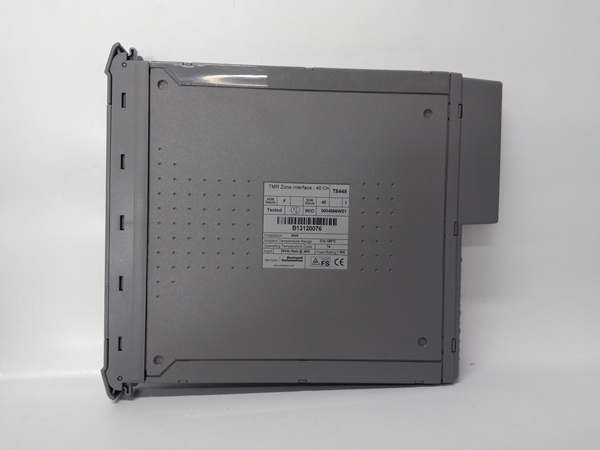
Total Channels: 40 TMR configurable I/O points (5 power groups × 8 channels each)
-
Channel Configuration: Per-channel selectable as analog input (4-20mA), digital input, or digital output
-
Analog Input Range: 4-20 mA (standard), 0-32 Vdc measurement capability
-
Digital Input Impedance: 33 kΩ
-
Digital Output Rating: 2 A max per channel, 3 A max per power group
-
Output On-State Resistance: 1.6 Ω max
-
Output Off-State Resistance: 33 kΩ
-
Minimum Load Current: 50 mA (digital output on-state)
-
Analog Resolution: 12-bit sigma-delta ADC
-
Measurement Accuracy: ±0.5% of reading + 1 count (current/voltage)
-
Safety Accuracy: 0.25 V (digital thresholds)
-
Field Voltage Range: 18-32 Vdc
-
Backplane Supply: 20-32 Vdc, 27 W max
-
Isolation Ratings:
-
50 V reinforced continuous (power group to power group, field common)
-
250 V basic fault (channel to channel within power group)
-
2500 V impulse withstand (system to field)
-
-
Turn-On/Turn-Off Delay: 5 ms typical
-
SOE Resolution: 1 ms timestamp accuracy
-
Operating Temperature: 0°C to +60°C (standard), -40°C to +70°C (extended variants)
-
Hot-Swap: Supported via Companion Slot or SmartSlot architecture
-
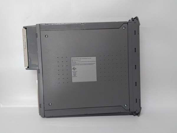
Physical: 266 mm H × 31 mm W × 303 mm D, 1.3 kg (2.87 lbs)
-
Safety Certification: TÜV IEC 61508 SIL 3

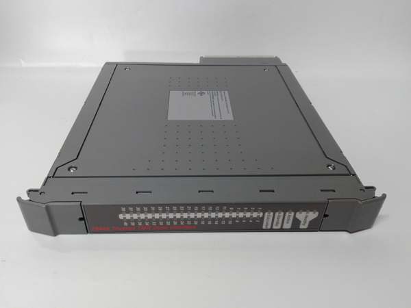
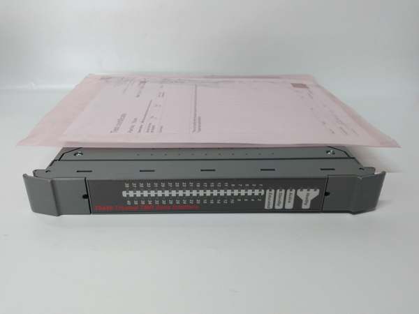
ICS Triplex T8448
The Real-World Problem It Solves
Fire & Gas detection systems can’t afford blind spots or single-point failures—one missed gas leak or false suppression discharge can mean the difference between a controlled shutdown and a catastrophic event. The T8448 eliminates this risk by providing 40 channels of triple-modular-redundant I/O that can be configured on-the-fly for different device types in the same safety zone. It handles the messy reality of mixed signal types (4-20mA gas detectors, digital break-glass contacts, high-power suppression solenoids) while maintaining SIL 3 integrity and electrical isolation between hazardous zones.
Where you’ll typically find it:
-
Offshore platform fire & gas detection loops with mixed smoke, heat, and combustible gas sensors
-
Petrochemical plant suppression system control cabinets driving CO2/Halon release solenoids
-
Refinery unit emergency shutdown zones combining process transmitters and manual E-stop stations
This module consolidates zone I/O into one TMR card—no more cobbling together separate analog and digital modules with inter-card wiring nightmares.
Hardware Architecture & Under-the-Hood Logic
The T8448 isn’t a dumb I/O aggregator—it’s a distributed signal conditioning system with three independent measurement paths per channel. Each of the 40 channels contains triplicated analog-to-digital converters and output drivers that vote their data 2-out-of-3 before reaching the IMB backplane. The module supports per-channel configuration via the System.INI file, allowing you to mix 4-20mA loops with digital contacts in the same power group without hardware changes.
Internal Signal Flow:
-
Channel Configuration: TriStation 1131 downloads per-channel settings (analog vs. digital, thresholds, power group assignments) to the module’s three independent processors during initialization
-
Signal Conditioning: Each channel’s field signal passes through three separate input circuits with individual isolation barriers and sigma-delta ADCs (for analog) or comparator chains (for digital)
-
Power Group Isolation: Channels are electrically grouped into 5 isolated zones (8 channels each) with 50V reinforced isolation between groups—faults in one zone can’t propagate to others
-
2oo3 Voting: The three channel processors exchange measurement data via the IMB; analog values are voted numerically, digital states are voted logically
-
Line Monitoring: For digital outputs, the module sources test currents during off-states to detect short circuits; for inputs, open-circuit detection requires external line monitoring devices
-
SOE Logging: State changes and fault conditions are timestamped with 1ms resolution and buffered for retrieval by the T8013 SOE Historian
ICS Triplex T8448
Field Service Pitfalls: What Rookies Get Wrong
Assuming “Configurable I/O” Means “Wire It Any Which Way”
The T8448’s flexibility is a double-edged sword. Engineers wire 4-20mA gas detectors and 24V digital outputs in the same power group, then wonder why they’re getting ground loop noise on the analog readings. The 50V isolation between power groups is reinforced, not absolute—high-current digital switching can induce millivolt-level noise on adjacent analog channels if you don’t respect zone boundaries.
-
Field Rule: Keep analog inputs (gas detectors, transmitters) in dedicated power groups separate from digital outputs (solenoids, relays). Use Power Groups 1-2 for analog, 3-5 for digital. If you must mix signals, put the noisiest devices (high-current solenoids) in Group 5 and the most sensitive analogs in Group 1, with unused channels as buffers between them. Check the “Group Isolation Status” in TriStation diagnostics—any reading below 45V indicates degradation.
Forgetting the 50mA Minimum Load on Digital Outputs
The T8448’s digital outputs need 50mA minimum to maintain the on-state and verify circuit continuity. Rookies wire them to high-impedance pilot relays or LED indicators drawing 10-20mA, then get “Open Circuit” faults even though the output LED is lit.
-
Quick Fix: Calculate your load current before commissioning. If your device draws <50mA, add a parallel loading resistor (470Ω, 2W for 24V systems) across the output terminals to sink the difference. For very light loads (solid-state relays), consider using the T8461 digital output module instead—it has a lower minimum load requirement. Always verify with a clamp meter: if the output is “on” but current is <50mA, you’ll get nuisance faults.
Enabling Short-Circuit Detection Without the Template
The T8448 can detect short circuits in digital output wiring, but only if you’ve configured the short-circuit detection template in the System.INI file. Junior engineers enable the diagnostic bit in TriStation but don’t load the template, then complain the module misses welded contacts.
-
Field Rule: The short-circuit template defines the expected impedance signature for each output in the de-energized state. You must customize this per application—there’s no universal default. Download the template via the TriStation “Module Configuration” dialog after setting up your field wiring. Test it by deliberately shorting a spare output with a jumper; the module should flag the fault within 100ms. If it doesn’t, your template is wrong or the feature isn’t enabled.


